Moxa TCC-100 Series User’s Guide Eighth Edition, February 2009 www.moxa.com/product © 2009 Moxa Inc. All rights reserved. Reproduction without permission is prohibited.
Moxa TCC-100 Series User’s Guide The software described in this manual is furnished under a license agreement and may be used only in accordance with the terms of that agreement. Copyright Notice Copyright © 2009 Moxa Inc. All rights reserved. Reproduction without permission is prohibited. Trademarks MOXA is a registered trademark of Moxa Inc. All other trademarks or registered marks in this manual belong to their respective manufacturers.
Table of Contents Chapter 1 Introduction............................................................1-1 Overview ...........................................................................1-2 Product Features................................................................1-4 Package Checklist .............................................................1-4 Product Specifications ......................................................1-5 Schematic .............................................................
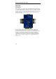
1 C h a p t e r 1 Introduction TCC-100 Series is an RS-232 to RS-422/485 media converter. Note that TCC-100I/TCC-100I-T comes with 2 KV isolation protection.
Moxa TCC-100 Series User’s Guide Overview Introduction Many important devices used in today’s industrial environment are still designed for use with an RS-232 interface. The reason is due in part to tradition, and in part to convenience. RS-232 hardware is relatively easy to design, and the device can be readily connected to most PCs. The drawback is that RS-232 is a point-to-point interface, and it imposes a distance limitation of only 15 meters between the device and the computer.
Introduction TCC-100 Series provides isolation protection for users who need an industrial grade interface conversion product to extend RS-232 transmission distance and increase networking capability. Its superior industrial application design, which includes DIN-Rail mounting, terminal block wiring, external terminal block power, and optical isolation for system protection, makes TCC-100 Series suitable for use in critical industrial environments.
Moxa TCC-100 Series User’s Guide Auto Baud Rate Detection TCC-100 Series incorporates a method for automatically detecting the serial signal’s baud rate by hardware. This is an extremely convenient feature for the user. Even if a device’s baud rate changes, the signal will still be transmitted through the RS-232 to RS-422/488 converter without any problem.
Introduction Product Specifications Model Names Communication RS-232 Signal RS-422/485 Signal RS-485 Data Direction Control Baud Rate ESD Protection Isolation TCC-100 Series Supports Tx, Rx, RTS, CTS; Female DB9 interface Terminal Block connector (DIP Switch selectable) 4-wire RS-422 (with RTS/CTS), up to 10 nodes (1.2 km) 4-wire RS-485: up to 32 nodes (1.2 km) 2-wire RS-485: up to 32 nodes (1.2 km) ADDC™ 50 bps to 921.
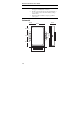
Moxa TCC-100 Series User’s Guide WARNING 1. 2. 3. This unit is not meant to be sold to consumers. It will only be shipped to manufacturers of factories. The DC source should come from an external adapter or 12 to 48 VDC source (not from DC mains) by using a transfer device. This unit should be installed or set up by a qualified service person. Schematic 11.5 mm 22 mm 67 mm O7 43 mm O3.5 O4 28.7 mm 1-6 100.4 mm 28.
Introduction LED Indicators TCC-100 Series’s top panel contains three LED indicators, as described in the following table: LED Name LED Function PWR Red indicates the power is on. Green indicates TCC-100 Series is receiving data from the RS-232 port. RED PWR GREEN YELLOW Yellow indicates TCC-100 Series is receiving data from the RS-422/485 port.
2 Chapter 2 Installation This chapter includes information about how to install TCC-100 Series, as well as function and block diagrams.
Moxa TCC-100 Series User’s Guide Hardware Installation Installing TCC-100 Series involves five straightforward steps: • • • • • STEP 1: Set the DIP Switches STEP 2: Attach the Power Supply STEP 3: Wire the Terminal Block STEP 4: Attach the RS-232 Converter STEP 5: Test the Connection The details of each of these five steps are described next. STEP 1: Set the DIP Switches The DIP Switches on TCC100/100I are used to set the signal transmission mode and enable or disable the termination resistor.
Installation Dip Switch Settings SW1 SW2 SW3 ON ON ON SW1 SW2 SW3 ON ON OFF SW1 SW2 SW3 OFF ON ON SW1 SW2 SW3 OFF ON OFF SW1 SW2 SW3 OFF OFF ON SW1 SW2 SW3 OFF OFF OFF RS-422 Terminator active 1 2 3 1 2 3 1 2 3 1 2 3 1 2 3 1 2 3 RS-422 4-wire RS-485 Terminator active 4-wire RS-485 2-wire RS-485 with Terminator 2-wire RS-485 2-3
Moxa TCC-100 Series User’s Guide The newly implemented DIP-2 Switches are used to configure the pull high/low resistors for different applications. Pull High/Low Resistor DIP-2 SW1 150K OFF 1K (default) ON NOTE 2-4 DIP-2 SW2 OFF ON We recommend setting the pull high/low resistor to 1K (ON/ON) when termination is enabled.
Installation V+ V- STEP 2: Attach the Power Supply + Power Supply 12 - 48 VDC TCC-100 Series is powered by an external 12 to 48 VDC power supply. To connect the power supply, run two wires from the V+ and V- terminals on TCC’s 3-connector terminal block to the DC power supply, as shown in the figure. Once the power supply is connected to its power source, the PWR LED located on TCC’s top panel should become illuminated in red. NOTE: TCC-100 Series provides reverse power protection. I.e.
Moxa TCC-100 Series User’s Guide Rx+ RxTx+ TxCTS+ CTSRTS+ RTSSGND Tx+(B) Tx-(A) Rx+(B)(Data+) Rx-(A)(Data-) RTS+(B) RTS-(A) Optional CTS+(B) CTS-(A) SGND STEP 4: Attach the RS-232 Connector Depending on your application, use the appropriate serial cable to connect from CC-100/100I’s RS-232 Female DB9 port to your RS-232 device, or to your computer’s COM port. RS-422 When using the RS-422 wiring option, first follow the 4-wire RS-485 wiring instructions given above.
Installation Termination Resistor Diagram Termination is designed to Termination Resistor: mitigate noise from the S3 On to Enable S3 Off to Disable RS-422/485 transmission signals. If the network cable is R too long, undesirable transmission-line effects will RxD+ arise. The best method for RxDmitigating energy on an unused conductor is to dissipate the energy as heat by terminating both ends of the unused conductor to ground with resistors (so-called bi-directional termination).
Moxa TCC-100 Series User’s Guide Isolation Block Diagram +5V +5V Data Output Optical Isolator Data Input +5V + V+ +5V Regulated Power Supply V- Local Power 12-30 VDC Typical Applications RS-485 Application A typical RS-485 application for TCC-100 Series is depicted in the following figure. In this scenario, two TCC-100 Series units are used to connect two PCs to an RS-485 network. The third TCC-100 Series is used to connect the PLC— which is designed for the RS-232 interface—to the RS-485 network.
Installation RS-422 Application RS- 422/485 Rx (A)(Data ) Rx+(B)(Data +) Tx (A) Tx+(B) RS-232 to RS-422/485 converter RTS+(B) RS -232 RTS (A) Transio DC9~30V CTS (A) CTS+(B) RS-232 Tx V V+ SGND RS-232 Rx V+ V DC9~30V TCC-100 MOXA TCC-100 Series SGND RS -232 RS-422 Point-to-Point Communication RS- 422/485 RTS (A) CTS (A) Transio Rx (A)(Data ) RTS+(B) CTS+(B) RS-232 to RS-422/485 converter PWR Tx (A) RS-232 Tx PC Tx+(B) Rx+(B)(Data +) PWR RS-232 Rx(+/-) Tx(+/-) w/ optional R