TCF-142 Series Quick Installation Guide Version 16.1, January 2021 Technical Support Contact Information www.moxa.com/support 2021 Moxa Inc. All rights reserved.
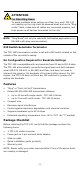
Overview Introduction TCF-142 series converters are equipped with a multiple interface circuit that can handle RS-232, RS-422, and RS-485 serial interfaces, as well as multi-mode or single-mode fiber. TCF-142 converters are used to extend serial transmission distance up to 5 km (TCF-142-M, with multi-mode fiber) or up to 40 km (TCF-142-S, with single-mode fiber). The TCF-142 must be configured to transmit a particular serial interface. You cannot transmit both RS-232 and RS-485 signals at the same time.
ATTENTION For Fiber Ring Users: To avoid problems when setting up a fiber ring, each TCF-142 unit making up the ring must be powered down and set to “Ring mode.” Next, make sure all cables are connected properly, and then power up all devices connected to the ring. NOTE “Ring Mode” can only be used with half-duplex applications (i.e., RS-485 multi-drop communication).
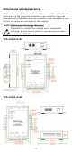
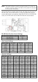
Dimensions and Appearance TCF-142 fiber converters are easy to set up and use. The serial terminal block of one of the converters connects to your computer, the serial terminal block of the other converter connects to your serial device, and the two converters are connected by fiber cable(s). NOTE Electrostatic Discharge Warning! To protect the product from damage due to electrostatic discharge, we recommend wearing a grounding device when handling your TCF-142.
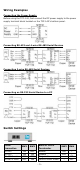
Wiring Examples Connecting the Power Supply Before using the TCF-142, first connect the DC power supply to the power supply terminal block located on the TCF-142’s bottom panel.
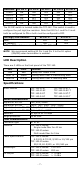
NOTE This switch setting is used for product revision 3.2 or later; for previous revisions, refer to the label on the product's rear panel for the correct information. The S1 DIP Switch is located inside the TCF-142. When the TCF-142 is in RS-485 mode, use this DIP switch to configure RS-485 data direction control, data format, and baudrate. When the TCF-142 is in RS-232/422 mode, the S1 DIP switch cannot affect RS-232/422 communication.
Baudrate 57600 115200 230400 460800 921600 S1 Pin 5 ON OFF ON OFF ON S1 Pin 6 ON ON OFF OFF ON S1 Pin 7 ON ON ON ON OFF S1 Pin 8 ON ON ON ON ON S1 Pin 9 OFF OFF OFF OFF OFF The S2 DIP switch is located inside the TCF-142. This switch is used to configure the pull high/low resistors. Note that S2 Pin 1 and Pin 2 must both be configured to ON or both must be configured to OFF. Pull High/Low Resistor S2 Pin 1* 150K OFF 1K (default) ON * These DIP switches are located inside the TCF-142.
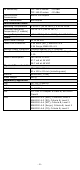
RX Sensitivity Point-to-Point Transmission Ring Transmission Environmental Limits Operating Temperature Extended Operating Temperature (T models) Storage Temperature Power Input Power Voltage Power Line Protection TCF-142-S series: TCF-142-M series: Half or Full duplex -25 dBm -20 dBm Half duplex 0 to 60°C (32 to 140°F), 5 to 95 % RH -40 to 75°C (-40 to 167°F) -40 to 75°C (-40 to 167°F), 5 to 95 % RH 12 to 48 VDC 1 kV Burst (EFT), EN61000-4-4 1 kV Surge, EN61000-4-5 Reverse Power Protection Protects aga