UC-7101 Hardware User’s Manual Fourth Edition, April 2009 www.moxa.com/product © 2009 Moxa Inc. All rights reserved. Reproduction without permission is prohibited.
UC-7101 Hardware User’s Manual The software described in this manual is furnished under a license agreement and may be used only in accordance with the terms of that agreement. Copyright Notice Copyright © 2009 Moxa Inc. All rights reserved. Reproduction without permission is prohibited. Trademarks MOXA is a registered trademark of Moxa Inc. All other trademarks or registered marks in this manual belong to their respective manufacturers.
Table of Contents Chapter 1 Introduction ..................................................................................................1-1 Overview.................................................................................................................................. 1-2 Package Checklist .................................................................................................................... 1-2 Product Features .....................................................................
1 Chapter 1 Introduction The Moxa UC-7101 series of embedded computers are mini, RISC-based, box-type computers that feature 10/100 Mbps Ethernet ports, RS-232/422/485 serial ports, and an ARM9 processor. The computers come with Linux pre-installed. In addition, the UC-7101 has an internal SD socket for storage expansion to offer high performance communication with unlimited storage in a super-compact, palm-size box.
UC-7101 Hardware User’s Manual Introduction Overview The UC-7101 series of mini, RISC-based communication platforms are ideal for embedded applications. All computers in the series come with RS-232/422/485 serial ports and 10/100 Mbps Ethernet LAN ports to provide users with a versatile communication platform. The UC-7101 series computers use the Moxa ART ARM9 192 MHz RISC CPU.
UC-7101 Hardware User’s Manual Introduction Product Features The UC-7101 series computers have the following features: y y y y y y y y y y y y Moxa ART ARM9 32-bit 192 MHz processor 16 MB RAM (about 12 MB of user programmable space) 8 MB Flash ROM (about 4 MB of user programmable space) One 10/100 Mbps Ethernet port for network redundancy One software-selectable RS-232/422/485 ports Select Any Baudrate from 50 bps to 921.
UC-7101 Hardware User’s Manual Introduction Power Requirements Power Input 12 to 48 VDC Power Consumption 300 mA @ 12 VDC (UC-7101) Mechanical Dimensions (W¯D¯H) 67 ¯ 100.
UC-7101 Hardware User’s Manual Introduction Software Specifications—UC-7101 (μClinux) Kernel Version: Protocol Stacks: 2.6.
2 Chapter 2 Hardware Introduction The UC-7101 is compact, rugged embedded computers designed for industrial applications. The LED indicators on the computers’ outer casing help you monitor the performance of the computers, and assist in identifying trouble spots. The hardware platform is both reliable and stable, and allows you to devote the bulk of your attention to developing your own application. In this chapter, we cover the basic hardware of the UC-7101 series embedded computers.
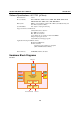
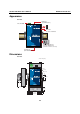
UC-7101 Hardware User’s Manual Hardware Introduction Appearance UC-7101 Ethernet (10/100BaseTx) 12 to 48 VDC RS-232 Console Terminal Internal SD Slot for Storage Expansion (remove cover to access) Serial Port (RS-232/422/485) Dimensions UC-7101 unit = mm (inch) 6 (0.24) 4 (0.16) 100.4 (3.95) 12.5 (0.49) 25 (0.98) 21.3 (0.8) 7 (0.28) 43.3 (1.67) 22 (0.87) 67 (2.64) 78 (3.07) 90 (3.
UC-7101 Hardware User’s Manual Hardware Introduction Panel Views UC-7101 Top View Reset Button Terminal Block Power Input RJ45 10/100 Mbps Ethernet Ports Nameplate View DIN-Rail screw hole Wallmount screw hole Bottom View DB9 (male) Serial Port 2-3
UC-7101 Hardware User’s Manual Hardware Introduction LED Indicators The following table shows the functions of the five LED indicators located on the front panel of the UC-7101 embedded computers. LED Name Ready P1 (Tx) P1 (Rx) LED Color Green Green LED Function Power is on and functioning normally. Serial port 1 is transmitting data. Off Serial port 1 is not transmitting data. Yellow Serial port 1 is receiving data. Off Serial port 1 is not receiving data.
UC-7101 Hardware User’s Manual Hardware Introduction ATTENTION This function only takes effect when the user directory is working correctly. If the user directory has crashed, the kernel will automatically load the factory defaults. Real Time Clock The real time clock in the UC-7101 embedded computers is powered by a lithium battery. We strongly recommend that you get help from Moxa’s technical support team to replace the lithium battery.
3 Chapter 3 Hardware Connection Description In this chapter, we show how to connect the UC-7101 embedded computer to the network and to various devices.
UC-7101 Hardware User’s Manual Hardware Connection Description Wiring Requirements This section explains how to connect the UC-7101 to serial devices. You should heed the following safety precautions before installing any electronic device: y Use separate paths for power wiring and wiring for devices. If power wiring and device wiring paths must cross, make sure the wires are perpendicular at the intersection point.
UC-7101 Hardware User’s Manual Hardware Connection Description ATTENTION This product should be mounted on a well-grounded mounting surface such as a metal panel. SG V- V+ SG: The Shielded Ground (sometimes called Protected Ground) contact is the left most contact of the 3-pin power terminal block connector when viewed from the angle shown in the figure at the left. Connect the SG wire to an appropriate grounded metal surface.
UC-7101 Hardware User’s Manual Hardware Connection Description Connecting to a Serial Device Connect the serial cable between the UC-7101 and the serial device(s). The two serial ports (P1 and P2) use male DB9 connectors, and can be configured for RS-232/422/485 by software.
UC-7101 Hardware User’s Manual Hardware Connection Description Installing a Secure Digital (SD) Memory Card UC-7101 The SD slot is located on the right side of the UC-7101 enclosure. To install an SD card, you must first remove the protective cover to access the slot, and then plug the SD card directly into the slot. Step 1: Use a screwdriver to remove the screws holding the SD card slot’s outer cover. Step 2: After removing the cover, insert the SD memory card into the slot.