UC-7112 LX Plus UC-7112, UC-7110, Hardware User’s Manual Fifth Edition, June 2009 www.moxa.com/product © 2009 Moxa Inc. All rights reserved. Reproduction without permission is prohibited.
UC-7112 LX Plus, UC-7112, UC-7110 Hardware User’s Manual The software described in this manual is furnished under a license agreement and may be used only in accordance with the terms of that agreement. Copyright Notice Copyright © 2009 Moxa Inc. All rights reserved. Reproduction without permission is prohibited. Trademarks MOXA is a registered trademark of Moxa Inc. All other trademarks or registered marks in this manual belong to their respective manufacturers.
Table of Contents Chapter 1 Introduction ..................................................................................................1-1 Overview.................................................................................................................................. 1-2 Package Checklist .................................................................................................................... 1-2 Product Features .....................................................................
1 Chapter 1 Introduction The Moxa UC-71xx series of embedded computers (UC-7110, UC-7112, and UC-7112 Plus) are mini, RISC-based, box-type computers that feature dual 10/100 Mbps Ethernet ports, two RS-232/422/485 serial ports, and an ARM9 processor. The computers come with Linux pre-installed. In addition, the UC-7112 Plus and UC-7112 have an internal SD socket for storage expansion to offer high performance communication with unlimited storage in a super-compact, palm-size box.
UC-7112 LX Plus UC-7112, UC-7110 User’s Manual Introduction Overview The UC-71xx series of mini, RISC-based communication platforms are ideal for embedded applications. All three computers in the series (UC-7110, UC-7112, and UC-7112 Plus) come with 2 RS-232/422/485 serial ports and dual 10/100 Mbps Ethernet LAN ports to provide users with a versatile communication platform. The UC-71xx series computers use the Moxa ART ARM9 192 MHz RISC CPU.
UC-7112 LX Plus UC-7112, UC-7110 User’s Manual Introduction Each model is shipped with the following items: y y y y y y y 1 UC-7110 or UC-7112 or UC-7112 Plus Quick Installation Guide Document & Software CD Ethernet Cable: RJ45 to RJ45 cross-over cable, 100 cm CBL-4PINDB9F-100: 4-pin header to DB9 female console port cable, 100 cm Universal Power Adaptor Product Warranty Statement Optional Accessories y 35 mm DIN-Rail Mounting Kit (DK-35A) NOTE: Please notify your sales representative if any of the ab
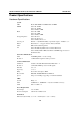
UC-7112 LX Plus UC-7112, UC-7110 User’s Manual Introduction Product Specifications Hardware Specifications System CPU DRAM Flash Storage Expansion Console port Button Other OS Moxa ART ARM9 32-bit RISC CPU, 192 MHz UC-7110: 16 MB UC-7112: 16 MB UC-7112 Plus: 32 MB UC-7110: 8 MB UC-7112: 8 MB UC-7112 Plus: 16 MB UC-7110: None UC-7112: SD slot ¯ 1 UC-7112 Plus: SD slot ¯ 1 RS-232 ¯ 1 (TxD, RxD, GND), 4-pin header output, “115200, n, 8, 1” Reset button ¯ 1, supports “Reset to Factory Default” RTC, buzzer
UC-7112 LX Plus UC-7112, UC-7110 User’s Manual Weight 190 g Construction Material aluminum, 1 mm Mounting DIN-rail, Wall-mounting Environment Operating Temperature Introduction -10 to 60°C (14 to 140°F), 5 to 95% RH -40 to 75°C (-40 to 167°F) for -T models Storage Temperature -20 to 80°C (-4 to 176°F), 5 to 95% RH -40 to 85°C (-40 to 185°F) for -T models Anti-Vibration 1 g @ IEC-68-2-6, sine wave (resonance search), 5-500 Hz, 1 Oct/min, 1 cycle, 13 mins 17 sec per axis (UC-7110 only) Regulatory
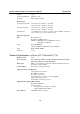
UC-7112 LX Plus UC-7112, UC-7110 User’s Manual Introduction Software Specifications—Linux (UC-7112 Plus) Kernel Version: Boot Loader: Protocol Stacks: File System: System Utilities: 2.6.9 Redboot TCP, UDP, IPv4, SNMP V1, ICMP, IGMP, ARP, HTTP, CHAP, PAP, SSH 1.0/ 2.
2 Chapter 2 Hardware Introduction The UC-7110, UC-7112, and UC-7112 Plus are compact, rugged embedded computers designed for industrial applications. The LED indicators on the computers’ outer casing help you monitor the performance of the computers, and assist in identifying trouble spots. The hardware platform is both reliable and stable, and allows you to devote the bulk of your attention to developing your own application.
UC-7112 LX Plus UC-7112, UC-7110 User’s Manual Hardware Introduction Appearance The front view of the UC-7112 is shown in the following figure. The UC-7110 and UC-7112 Plus look the same, except that the UC-7110 does not have an internal SD slot.
UC-7112 LX Plus UC-7112, UC-7110 User’s Manual Hardware Introduction Panel Views The three main panel views of the UC-7110, UC-7112, and UC-7112 Plus are shown below: Top View Reset Button Terminal Block Power Input RJ45 10/100 Mbps Ethernet Ports Front View V+ RESET LAN1 LAN2 12-48V Ready TX P1 DIN-Rail screw hole RX TX P2 RX UC-7110 Universal Communicator Wallmount screw hole RS-232/422/485 P1 P2 Bottom View DB9 (male) Serial Ports LED Indicators The following table shows the functions
UC-7112 LX Plus UC-7112, UC-7110 User’s Manual Hardware Introduction Internal SD Socket The UC-7112 and UC-7112 Plus have an internal SD socket for storage expansion. For the UC-7112, a Secure Digital (SD) memory card compliant with the SD 1.0 standard can be used to provide up to 1 GB of additional memory space. In addition, the UC-7112 Plus supports Secure Digital High Capacity (SDHC) memory cards that are compliant with the SD 2.
UC-7112 LX Plus UC-7112, UC-7110 User’s Manual Hardware Introduction Real Time Clock The real time clock in the UC-71xx embedded computers is powered by a lithium battery. We strongly recommend that you get help from Moxa’s technical support team to replace the lithium battery. If the battery needs to be changed, contact the Moxa RMA service team for RMA service. ATTENTION The battery may explode if replaced by an incorrect type.
3 Chapter 3 Hardware Connection Description In this chapter, we show how to connect the UC-71xx embedded computer to the network and to various devices.
UC-7112 LX Plus UC-7112, UC-7110 User’s Manual Hardware Connection Description Wiring Requirements This section explains how to connect the UC-71xx embedded computers to serial devices. You should heed the following safety precautions before installing any electronic device: y Use separate paths for power wiring and wiring for devices. If power wiring and device wiring paths must cross, make sure the wires are perpendicular at the intersection point.
UC-7112 LX Plus UC-7112, UC-7110 User’s Manual Hardware Connection Description ATTENTION This product should be mounted on a well-grounded mounting surface such as a metal panel. SG V- V+ SG: The Shielded Ground (sometimes called Protected Ground) contact is the left most contact of the 3-pin power terminal block connector when viewed from the angle shown in the figure at the left. Connect the SG wire to an appropriate grounded metal surface.
UC-7112 LX Plus UC-7112, UC-7110 User’s Manual Hardware Connection Description Connecting to a Serial Device Connect the serial cable between the UC-71xx and the serial device(s). The two serial ports (P1 and P2) use male DB9 connectors, and can be configured for RS-232/422/485 by software.