UC-7402 User’s Manual Fourth Edition, February 2009 www.moxa.com/product © 2009 Moxa Inc. All rights reserved. Reproduction without permission is prohibited.
UC-7402 User’s Manual The software described in this manual is furnished under a license agreement and may be used only in accordance with the terms of that agreement. Copyright Notice Copyright © 2009 Moxa Inc. All rights reserved. Reproduction without permission is prohibited. Trademarks MOXA is a registered trademark of Moxa Inc. All other trademarks or registered marks in this manual belong to their respective manufacturers.
Table of Contents Chapter 1 Introduction ..................................................................................................1-1 Overview.................................................................................................................................. 1-2 Package Checklist....................................................................................................... 1-2 Product Features ...................................................................................
Loading Factory Defaults ........................................................................................... 3-5 Enabling and Disabling Daemons............................................................................................ 3-5 Setting the Run-Level .............................................................................................................. 3-8 Adjusting the System Time .....................................................................................................
1 Chapter 1 Introduction Moxa UC-7402 is a web server embedded network computer that features dual 10/100 Mbps Ethernet ports, a PCMCIA interface for wireless LAN communication, and CompactFlash for mass storage disk expansion. UC-7402 is an excellent choice for embedded network applications and diverse M2M solutions. UC-7402 is a rugged, compact embedded computer that is designed for industrial applications.
UC-7402 User’s Manual Introduction Overview Moxa UC-7402, a web server embedded network computer features dual 10/100 Mbps Ethernet ports, a PCMCIA interface for wireless LAN communication and CompactFlash for mass storage disk expansion. UC-7402 uses an Intel XScale IXP422 266 Mhz RISC CPU.
UC-7402 User’s Manual Introduction Product Hardware Specifications CPU RAM Flash LAN LAN Protection Serial Console/PPP USB 1.1 Client PCMCIA Compact Flash Real Time Clock Buzzer LEDs Power input Power Consumption Dimensions Gross Weight Operating temperature Storage temperature Regulatory Approvals Warranty UC-7402-LX Intel Xscale IXP422, 266 MHz 128 MB 32 MB Auto-sensing 10/100 Mbps x 2 Built-in 1.
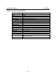
UC-7402 User’s Manual Introduction Hardware Introduction Appearance and Dimensions Appearance UC-7402 Rear View 12-48 VDC Power Input DC 12-48V V+ V- 10/100 Mbps Ethernet x 2 PCMCIA LAN1 LAN2 Console CF CF x 1 PCMCIA x 1 USB 1.
UC-7402 User’s Manual Introduction 44 mm [1.73"] 125 mm [4.92"] Dimensions 197 mm [7.76"] Hardware Block Diagram The following block diagram shows the layout of UC-7402’s internal components.
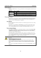
UC-7402 User’s Manual Introduction LED Indicators UC-7402 has 4 LED indicators on the top panel. Refer to the following table for information about each LED. LED Name Ready LAN1, LAN2 Console Color Green Yellow Green Yellow Green Meaning Power is ON, and system is ready (after booting up) 10 Mbps Ethernet connection 100 Mbps Ethernet connection Console port is receiving RX data from the serial device. Console port is transmitting TX data to the serial device.
UC-7402 User’s Manual Introduction Real Time Clock UC-7402’s real time clock is powered by a lithium battery. We strongly recommend that you do not replace the lithium battery without help from a qualified Moxa support engineer. If you need to change the battery, contact Moxa RMA service team. WARNING There is a risk of explosion if the battery is replaced by an incorrect type.
UC-7402 User’s Manual Introduction DIN-Rail Mounting The aluminum DIN-Rail attachment plate is included in the package. If you need to reattach the DIN-Rail attachment plate to UC-7402, make sure the stiff metal spring is situated towards the top, as shown in the figures below. 1. Insert the top of the DIN-Rail into the slot just below the stiff metal spring. 2. The DIN-Rail attachment unit will snap into place as shown below.
UC-7402 User’s Manual Introduction You should also observe the following common wiring rules: y Use separate paths to route wiring for power and devices. If power wiring and device wiring paths must cross, make sure the wires are perpendicular at the intersection point. NOTE: Do not run signal or communication wiring and power wiring in the same wire conduit. To avoid interference, wires with different signal characteristics should be routed separately.
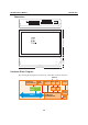
UC-7402 User’s Manual Introduction Connecting to the Network Connect one end of the Ethernet cable to one of UC-7402’s 10/100M Ethernet ports (8-pin RJ45) and the other end of the cable to the Ethernet network. If the cable is properly connected, UC-7402 will indicate a valid connection to the Ethernet in the following ways: 1 1 8 8 The bottom right corner LED indicator maintains a solid green color when the cable is properly connected to a 100 Mbps Ethernet network.
UC-7402 User’s Manual Introduction Software Introduction Software Architecture The Linux operating system that is pre-installed in UC-7402 follows the standard Linux architecture, making it easy to port programs that follow the POSIX standard to UC-7402. Porting is done with the GNU Tool Chain provided by Moxa. In addition to the Standard POSIX API, device drivers for the buzzer and CompactFlash mass storage, and Wireless LAN PCMCIA card are also included in the UC-7402 Linux system.
UC-7402 User’s Manual Introduction Normally, the kernel uses the User Root File System to boot up the system. The Mini Root File System is protected, and cannot be changed by the user, providing a “safe” zone. The kernel will only use the Mini Root File System when the User Root File System crashes. For more information about the memory map and programming, refer to Chapter 5, “Programmer’s Guide.
UC-7402 User’s Manual Introduction Software Package Redboot (V1.92) MontaVista embedded Linux 2.4.18 ARP, PPP, CHAP, PAP, IPv4, ICMP, TCP, UDP, DHCP, FTP, SNMP V1, HTTP, NTP, NFS, SMTP, SSH 1.0/2.
2 Chapter 2 Getting Started In this chapter, we explain how to connect UC-7402, turn on the power, and then get started using the programming and other functions. The following topics are covered in this chapter: Powering on UC-7402 Connecting UC-7402 to a PC ¾ Serial Console ¾ Telnet Console ¾ SSH Console Configuring the Ethernet Interface ¾ Modifying Network Settings with the Serial Console ¾ Modifying Network Settings over the Network Configuring the WLAN via the PCMCIA Interface ¾ IEEE802.
UC-7402 User’s Manual Getting Started Powering on UC-7402 Connect the SG wire to the Shielded Contact located in the upper left corner of the UC-7402, and then power on UC-7402 by connecting it to the power adaptor. It takes about 30 to 60 seconds for the system to boot up. Once the system is ready, the Ready LED will light up, and the Network address settings will appear on the LCM display.
UC-7402 User’s Manual Getting Started Telnet Console If you know at least one of the two IP addresses and netmasks, then you can use Telnet to connect to UC-7402’s console utility. The default IP address and Netmask for each of the two ports are given below: Default IP Address Netmask 192.168.3.127 255.255.255.0 LAN 1 192.168.4.127 255.255.255.0 LAN 2 Use a cross-over Ethernet cable to connect directly from your PC to UC-7402.
UC-7402 User’s Manual Getting Started ATTENTION Serial Console Reminder Remember to choose VT100 as the terminal type. Use cable CBL-RJ45F9-150, which comes with UC-7402, to connect to the serial console port. Telnet Reminder When connecting to UC-7402 over a LAN, you must configure your PC’s Ethernet IP address to be on the same subnet as the UC-7402 you wish to contact. If you do not get connected on the first try, re-check the serial and IP settings, and then unplug and re-plug UC-7402’s power cord.
UC-7402 User’s Manual Getting Started Linux Users From a Linux machine, use the “ssh” command to access UC-7402’s Console utility via SSH. #ssh 192.168.3.127 Select yes to complete the connection. [root@bee_notebook root]# ssh 192.168.3.127 The authenticity of host ‘192.168.3.127 (192.168.3.127)’ can’t be established. RSA key fingerprint is 8b:ee:ff:84:41:25:fc:cd:2a:f2:92:8f:cb:1f:6b:2f.
UC-7402 User’s Manual Getting Started Dynamic IP addresses: By default, UC-7402 is configured for “static” IP addresses. To configure one or both LAN ports to request an IP address dynamically, replace static with dhcp and then delete the address, network, netmask, and broadcast lines. Default Setting for LAN1 iface ixp0 inet static address 192.168.3.127 network: 192.168.3.0 netmask 255.255.255.0 broadcast 192.168.3.255 3.
UC-7402 User’s Manual NOTE Getting Started After changing the IP settings, use the networking restart command to activate the new IP address. Modifying Network Settings over the Network IP settings can be activated over the network, but the new settings will not be saved to the flash ROM without modifying the file /etc/network/interfaces. For example, type the command #ifconfig ixp0 192.168.1.1 to change the IP address of LAN1 to 192.168.1.1. Configuring the WLAN via the PCMCIA Interface IEEE802.
UC-7402 User’s Manual Getting Started Edit network.opts with the following command to edit Wireless LAN’s default setting. #vi /etc/pcmcia/network.opts 3. Configure the Wireless LAN card’s default SSID setting profile. (Default SSID is “any”) #vi /etc/wlan/wlan.conf // Consult your network administrator for SSID required in your wireless network. For example, SSID_waln0=”any”, Enable_wlan0=y// 4. Duplicate the configuration profile to a new profile.
UC-7402 User’s Manual Getting Started IEEE802.11g The following IEEE802.11g wireless modules are supported: y y y y y y ASUS—WL-107g CNET—CWC-854 (181D version) Edmiax—EW-7108PCg Amigo—AWP-914W GigaByte—GN-WMGK Other brands that use the Ralink RT2560 series chip set To configure the WLAN for IEEE802.11g: 1. Unplug the CardBus Wireless LAN card first. 2. Use the command #vi /etc/networking/interfaces to open the “interfaces” configuration file with vi editor, and then edit the 802.
UC-7402 User’s Manual 3. Getting Started Additional WLAN parameters are contained in the file RT2500STA.dat. To open the file, navigate to the RT2500STA folder and invoke vi, or type the following command #vi /etc/Wireless/RT2500STA/RT2500STA.dat to edit the file with vi editor. Setting options for the various parameters are listed below the figure.
UC-7402 User’s Manual Getting Started SSID—Sets the softAP SSID Setting Any 32-byte string NetworkType—Sets the wireless operation mode Setting Explanation Infra Infrastructure mode (uses access points to transmit data) Adhoc Adhoc mode (transmits data from host to host) Channel—Sets the channel Setting Explanation 0 auto 1 to 14 the channel you want to use AuthMode—Sets the authentication mode Setting OPEN SHARED WPAPSK WPANONE EncrypType—Sets encryption type Setting NONE WEP TKIP AES Default
UC-7402 User’s Manual Getting Started WpaPsk—Enables or disables TxBurst Setting Explanation 0 disable 1 enable TurboRate—Enables or disables TurboRate Setting Explanation 0 disable 1 enable BGProtection—Sets 11b/11g protection (this function is for engineering testing only) Setting Explanation 0 auto 1 always on 2 always off ShortSlot—Enables or disables the short slot time Setting Explanation 0 disable 1 enable TxRate—Sets the TxRate Setting Explanation 0 Auto 1 1 Mbps 2
UC-7402 User’s Manual Getting Started RTSThreshold—Sets the RTS threshold Setting 1 to 2347 FragThreshold—Sets the fragment threshold Setting 256 to 2346 Test Program—Developing Hello.c In this section, we use the standard “Hello” programming example to illustrate how to develop a program for UC-7402. In general, program development involves the following seven steps. Step 1: Connect UC-7402 to a Linux PC. Step 2: Install Tool Chain (GNU Cross Compiler & glibc).
UC-7402 User’s Manual Getting Started Checking the Flash Memory Space If the flash memory is full, you will not be able to save data to the Flash ROM. Use the following command to calculate the amount of “Available” flash memory: />df –h If there isn’t enough “Available” space for your application, you will need to delete some existing files. To do this, connect your PC to the UC-7402 with the console cable, and then use the console utility to delete the files from UC-7402’s flash memory.
UC-7402 User’s Manual NOTE Getting Started Be sure to type the #make command from within the /tmp/example/hello directory, since UC’s tool chain puts a specially designed Makefile in that directory. This special Makefile uses the mxscale-gcc compiler to compile the hello.c source code for the Xscale environment. If you type the #make command from any other directory, Linux will use the x86 compiler (for example, cc or gcc). Refer to Chapter 5 to see a Make file example.
3 Chapter 3 Managing Embedded Linux This chapter includes information about version control, deployment, updates, and peripherals. The information in this chapter will be particularly useful when you need to run the same application on several UC-7402 units.
UC-7402 User’s Manual Managing Embedded Linux System Version Information To determine the hardware capability of your UC-7402, and what kind of software functions are supported, check the version numbers of your UC-7402’s hardware, kernel, and user file system. Contact Moxa to determine the hardware version. You will need the Production S/N (Serial number), which is located on UC-7402’s bottom label. To check the kernel version, type: #kversion To check the user file system version, type: #fsversion 192.
UC-7402 User’s Manual Managing Embedded Linux Since different Flash disks have different sizes, it’s a good idea to check the size of your Flash disk before upgrading the firmware, or before using the disk to store your application and data files. Use the #df –h command to list the size of each memory block, and how much free space is available in each block. 192.168.3.127 – PuTTY root@Moxa:~# df -h Filesystem Size Used Available Use% Mounted on /dev/mtdblock3 26.0M 8.9M 17.1M 34% / /dev/mtdblock3 26.
UC-7402 User’s Manual Managing Embedded Linux local: UC7402-1.5.frm remote: UC7402-1.5.frm 200 Port command successful. 150 Opening data connection for UC7402-1.5.frm 226 Transfer complete. 13167772 bytes received in 2.17 secs (5925.8 kB/s) ftp> 3. Next, use the upfirm command to upgrade the kernel and root file system: #upfirm UC7402-x.x.x.frm 192.168.3.127 – PuTTY root@Moxa:/mnt/ramdisk# upfirm UC7402-1.5.frm Upgrade firmware utility version 1.0. To check source firmware file context.
UC-7402 User’s Manual Managing Embedded Linux Loading Factory Defaults The easiest way to load factory defaults is to update the firmware (follow the instructions in the previous section to upgrade the firmware). Note that if your user file is not working properly, the system will mount the Mini File System. In this case, you will need to load factory defaults to resume normal operation. Enabling and Disabling Daemons The following daemons are enabled when UC-7402 boots up for the first time. snmpd .....
UC-7402 User’s Manual Managing Embedded Linux Type the command “ps –ef” to list all processes currently running. 192.168.3.
UC-7402 User’s Manual Managing Embedded Linux Then you will find the enabled daemons after you reboot the system. 192.168.3.
UC-7402 User’s Manual Managing Embedded Linux Setting the Run-Level In this section, we outline the steps you should take to set the Linux run-level and execute requests. Use the following command to enable or disable settings: 192.168.3.127 – PuTTY root@Moxa:/ect/rc.d/rc3.d# ls S19nfs-common S25nfs-user-server S99showreadyled S20snmpd S55ssh S24pcmcia S99rmnologin root@Moxa:/etc/rc.d/rc3.d# #cd /etc/rc.d/init.d Edit a shell script to execute /root/tcps2-release and save to tcps2 as an example.
UC-7402 User’s Manual Managing Embedded Linux Adjusting the System Time Setting the Time Manually UC-7402 has two time settings. One is the system time, and the other is the RTC (Real Time Clock) time kept by the UC-7402 hardware. Use the #date command to query the current system time or set a new system time. Use #hwclock to query the current RTC time or set a new RTC time.
UC-7402 User’s Manual Managing Embedded Linux NTP Client UC-7402 has a built-in NTP (Network Time Protocol) client that is used to initialize a time request to a remote NTP server. Use #ntpdate to update the system time. #ntpdate time.stdtime.gov.tw #hwclock –w Visit http://www.ntp.org for more information about NTP and NTP server addresses. 10.120.53.100 – PuTTY root@Moxa:~# date ; hwclock Sat Jan 1 00:00:36 CST 2000 Sat Jan 1 00:00:37 2000 -0.
UC-7402 User’s Manual Managing Embedded Linux Cron—daemon to Execute Scheduled Commands Start Cron from the directory /etc/rc.d/rc.local. It will return immediately, so you don’t need to start it with ‘&’ to run the background. The Cron daemon will search /etc/cron.d/crontab for crontab files, which are named after accounts in /etc/passwd. Cron wakes up every minute, and checks each command to see if it should be run in the current minute. Modify the file /etc/cron.
4 Chapter 4 Managing Communications In this chapter, we explain how to configure UC-7402’s various communication functions.
UC-7402 User’s Manual Managing Communication Telnet / FTP In addition to supporting Telnet client/server and FTP client/server, the UC-7402 system also supports SSH and sftp client/server. To enable or disable the Telnet/ftp server, you first need to edit the file /etc/inetd.conf. Enabling the Telnet/ftp server The following example shows the default content of the file /etc/inetd.conf.
UC-7402 User’s Manual Managing Communication Web Service—Apache The Apache web server’s main configuration file is /etc/apache/httpd.conf, with the default homepage located at /usr/www/html/index.html. Save your own homepage to the following directory: /usr/www/html/ Save your CGI page to the following directory: /usr/www/cgi-bin/ Before you modify the homepage, use a browser (such as Microsoft Internet Explore or Mozilla Firefox) from your PC to test if the Apache Web Server is working.
UC-7402 User’s Manual Managing Communication To open the default CGI test script report page, type http://192.168.3.127/cgi-bin/test-cgi in your browser’s address box. NOTE The CGI function is enabled by default. If you want to disable the function, modify the file /etc/apache/httpd.conf. When you develop your own CGI application, make sure your CGI file is executable. 192.168.3.
UC-7402 User’s Manual Managing Communication Saving a Web Page to the CF Card Since some applications will have web pages that take up a lot of memory space, you will need to be able to run the homepage and other pages from the CF card. In this section, we use a simple example to illustrate how to save web pages to the CF card, and then configure the Apache web server to open the pages. The files used in this example can be downloaded from Moxa’s website. Step 1: Prepare web page and put pages to CF card.
UC-7402 User’s Manual Managing Communication Step 3: Use the following commands to restart the Apache web server: #cd /etc/init.d #./apache restart Step4: Open your browser and connect to the UC-7402 by typing the current LAN1 IP address in the browser’s address box. NOTE Visit the Apache website at http://httpd.apache.org/docs/ for more information about setting up an Apache server.
UC-7402 User’s Manual Managing Communication Source NAT (SNAT)—changes the first source packet IP address Destination NAT (DNAT)—changes the first destination packet IP address MASQUERADE—a special form for SNAT. If one host can connect to internet, then other computers that connect to this host can connect to the Internet when it the computer does not have an actual IP address. REDIRECT—a special form of DNAT that re-sends packets to a local host independent of the destination IP address. C.
UC-7402 User’s Manual Managing Communication UC-7402 supports the following sub-modules. Be sure to use the module that matches your application.
UC-7402 User’s Manual Managing Communication Examples: # iptables -L -n In this example, since we do not use the -t parameter, the system uses the default ‘filter’ table. Three chains are included: INPUT, OUTPUT, and FORWARD. INPUT chains are accepted automatically, and all connections are accepted without being filtered.
UC-7402 User’s Manual Managing Communication Example 3: Accept TCP packets from Class C network 192.168.1.0/24. # iptables –A INPUT –i ixp0 –p tcp –s 192.168.1.0/24 –j ACCEPT Example 4: Drop TCP packets from 192.168.1.25. # iptables –A INPUT –i ixp0 –p tcp –s 192.168.1.25 –j DROP Example 5: Drop TCP packets addressed for port 21. # iptables –A INPUT –i ixp0 –p tcp --dport 21 –j DROP Example 6: Accept TCP packets from 192.168.0.
UC-7402 User’s Manual 1. 2. 3. 4. 5. 6. Managing Communication #ehco 1 > /proc/sys/net/ipv4/ip_forward #modprobe #modprobe #modprobe #modprobe ip_tables ip_conntrack iptable_nat ipt_MASQUERADE #iptables -t nat –A POSTROUTING –o ixp0 –j SNAT --to-source 192.168.3.127 or 7. #iptables –t nat –A POSTROUTING –o ixp0 –j MASQUERADE Enabling NAT at Bootup In the most of real world situations, you will want to use a simple shell script to enable NAT when UC-7402 boots up. The following script is an example.
UC-7402 User’s Manual Managing Communication The pppd daemon is used to connect to a PPP server from a Linux system. For detailed information about pppd see the man page. Example 1: Connecting to a PPP server over a simple dial-up connection The following command is used to connect to a PPP server by modem. Use this command for old ppp servers that prompt for a login name (replace username with the correct name) and password (replace password with the correct password).
UC-7402 User’s Manual Managing Communication 192.1.1.17 This is a degenerate case of a general option of the form x.x.x.x:y.y.y.y. Here x.x.x.x is the local IP address and y.y.y.y is the IP address of the remote end of the PPP connection. If this option is not specified, or if just one side is specified, then x.x.x.x defaults to the IP address associated with the local machine’s hostname (located in /etc/hosts), and y.y.y.y is determined by the remote machine.
UC-7402 User’s Manual Managing Communication Try typing: netstat -nr This should show three routes, something like this: Kernel routing table Destination Gateway iface 129.67.1.165 0.0.0.0 ppp0 127.0.0.0 0.0.0.0 0.0.0.0 129.67.1.165 ppp0 Genmask Flags Metric Ref Use 255.255.255.255 UH 0 0 6 255.0.0.0 0.0.0.0 U UG 0 0 0 0 0 lo 6298 If your output looks similar but doesn’t have the destination 0.0.0.
UC-7402 User’s Manual 4. Managing Communication Edit the file /etc/ppp/chap-secrets and add the following: “username@hinet.net” * “password” * “username@hinet.net” is the username obtained from the ISP to log in to the ISP account. “password” is the corresponding password for the account. 5. Edit the file /etc/ppp/pap-secrets and add the following: “username@hinet.net” * “password” * “username@hinet.net” is the username obtained from the ISP to log in to the ISP account.
UC-7402 User’s Manual Managing Communication 6. Edit the file /etc/ppp/options and add the following line: plugin pppoe 7. Add one of two files: /etc/ppp/options.ixp0 or /etc/ppp/options.ixp1. The choice depends on which LAN is connected to the ADSL modem. If you use LAN1 to connect to the ADSL modem, then add /etc/ppp/options.ixp0. If you use LAN2 to connect to the ADSL modem, then add /etc/ppp/options.ixp1.
UC-7402 User’s Manual Managing Communication 8. Set up DNS If you are using DNS servers supplied by your ISP, edit the file /etc/resolv.conf by adding the following lines of code: nameserver ip_addr_of_first_dns_server nameserver ip_addr_of_second_dns_server For example: nameserver 168.95.1.1 nameserver 139.175.10.20 9. Use the following command to create a pppoe connection: pppd ixp0 The ixp0 is what is connected to the ADSL modem LAN port. The example above uses LAN1.
UC-7402 User’s Manual Managing Communication optionxx The option list for a machine describes the kind of access the machine will have. Important options are: ro Read only. This is the default. rw Readable and Writeable. no_root_squash If no_root_squash is selected, then the root on the client machine will have the same level of access to files on the system as the root on the server.
UC-7402 User’s Manual Managing Communication Setting up UC-7402 as an NFS Client The following procedure is used to mount a remote NFS Server. 1. 2. 3. Scan the NFS Server’s shared directory. Establish a mount point on the NFS Client site. Mount the remote directory to a local directory. Step 1: #showmount –e showmount: -e: HOST: HOST Show the mount information for an NFS Server. Show the NFS Server’s export list. IP address or DNS address.
UC-7402 User’s Manual Managing Communication SNMP UC-7402 has built-in SNMP V1 (Simple Network Management Protocol) agent software. It supports RFC1317 RS-232 like group and RFC 1213 MIB-II. The following simple example allows you to use an SNMP browser on the host site to query the UC-7402, which is the SNMP agent. UC-7402 will respond. ***** SNMP QUERY STARTED ***** 1: sysDescr.0 (octet string) Linux Moxa 2.4.18_mvl30-ixdp425 #1049 Tue Oct 26 09:34:15 CST 2004 armv5teb 2: sysObjectID.
UC-7402 User’s Manual Managing Communication The following tables list the variables supported by UC-7402. Open VPN This function is only available for firmware version V1.5 (and later versions). OpenVPN provides two types of tunnels for users to implement VPNS: Routed IP Tunnels and Bridged Ethernet Tunnels. Here we describe the second type of tunnel. To begin with, check to make sure that the system has a virtual device /dev/net/tun.
UC-7402 User’s Manual 3. Managing Communication Generate a script file named openvpn-bridge on each OpenVPN machine. This script reconfigures interface “ixp1” as IP-less, creates logical bridge(s) and TAP interfaces, loads modules, enables IP forwarding, etc. #---------------------------------Start----------------------------#!/bin/sh iface=ixp1 # defines the internal interface maxtap=`expr 1` # defines the number of tap devices. I.e.
UC-7402 User’s Manual Managing Communication { ifcfg_vpn if [ ! \( -d “/dev/net” \) ]; then mkdir /dev/net fi if [ ! \( -r “/dev/net/tun” \) ]; then # create a device file if there is none mknod /dev/net/tun c 10 200 fi # load modules “tun” and “bridge” mname=tun module_up mname=bridge module_up # create an ethernet bridge to connect tap devices, internal interface brctl addbr br0 brctl addif br0 $iface # the bridge receives data from any port and forwards it to other ports.
UC-7402 User’s Manual Managing Communication brctl delbr br0 ifconfig br0 down ifconfig $iface $IPADDR netmask $NETMASK broadcast $BROADCAST killall -TERM openvpn } case “$1” in start) start ;; stop) stop ;; restart) stop start ;; *) echo “Usage: $0 [start|stop|restart]” exit 1 esac exit 0 #---------------------------------- end ----------------------------- Create link symbols to enable this script at boot time: # ln -s /etc/openvpn/openvpn-bridge /etc/rc.d/rc3.
UC-7402 User’s Manual Managing Communication Note: Select cipher and authentication algorithms by specifying “cipher” and “auth”. To see with algorithms are available, type: # openvpn --show-ciphers # openvpn --show—auths 5. Start both of OpenVPN peers, # openvpn --config A-tap0-br.conf& # openvpn --config B-tap0-br.conf& If you see the line “Peer Connection Initiated with 192.168.8.173:5000” on each machine, the connection between OpenVPN machines has been established successfully on UDP port 5000. 6.
UC-7402 User’s Manual Managing Communication Setup 2: Ethernet Bridging for Private Networks on the Same Subnet 1. Set up four machines as shown in the following diagram: Host A local net OpenVPN A eth1: 192.168.2.173 eth0: 192.168.2.171 Internet eth0: 192.168.8.173 ixp0: 192.168.8.174 eth0: 192.168.2.172 ixp1: 192.168.2.174 Host B 2. OpenVPN B local net The configuration procedure is almost the same as for the previous example.
UC-7402 User’s Manual 2. Managing Communication Create a configuration file named “A-tun.conf” and an executable script file named “A-tun.sh”. # point to the peer remote 192.168.8.174 dev tun secret /etc/openvpn/secrouter.key cipher DES-EDE3-CBC auth MD5 tun-mtu 1500 tun-mtu-extra 64 ping 40 ifconfig 192.168.2.173 192.168.4.174 up /etc/openvpn/A-tun.sh #--------------------------------#!/bin/sh # value after “-net” is the subnet route add -net 192.168.4.
5 Chapter 5 Programmer’s Guide This chapter includes important information for programmers.
UC-7402 User’s Manual Programmer’s Guide Flash Memory Map Partition sizes are hard coded into the kernel binary. To change the partition sizes, you will need to rebuild the kernel. The flash memory map is shown in the following table.
UC-7402 User’s Manual Programmer’s Guide Obtaining help Use the Linux man utility to obtain help on many of the utilities provided by the tool chain. For example to get help on the armv5b-linux-gcc compiler, issue the command: #man armv5b-linux-gcc Cross Compiling Applications and Libraries To compile a simple C application, just use the cross compiler instead of the regular compiler: #mxscaleb-gcc –o example –Wall –g –O2 example.c #mxscaleb-strip –s example #mxscaleb-gcc -ggdb –o example-debug example.
UC-7402 User’s Manual Programmer’s Guide Uninstalling the Linux Tool Chain Use the command rpm –qa|grep mxscaleb to query if the Moxa tool chain is installed on the system. Use the command rpm -e mxscale-x.x.x-x to uninstall the Moxa Xscale tool chain.
UC-7402 User’s Manual Programmer’s Guide Debugging with GDB First compile the program must with option -ggdb. Use the following steps: 1. To debug a program called hello-debug on the target, use the command: #gdbserver 192.168.4.142:2000 hello-debug This is where 2000 is the network port number on which the server waits for a connection from the client. This can be any available port number on the target.
UC-7402 User’s Manual Programmer’s Guide Buzzer The device node is located at /dev/console. UC-7402 supports Linux standard buzzer control, with UC-7402’s buzzer running at a fixed frequency of 100 Hz. You must include . 1. Function: KDMKTONE ioctl(fd, KDMKTONE, unsigned int arg); Description: The buzzer’s behavior is determined by the argument arg. The “high word” part of arg gives the length of time the buzzer will sound, and the “low word” part gives the frequency.
UC-7402 User’s Manual Programmer’s Guide int swtd_enable(int fd, unsigned long time) Description Enable application sWatchDog. And you must do ack after this process. Input int fd - the file handle, from the swtd_open() return value. unsigned long time - The time you wish to ack sWatchDog periodically. You must ack the sWatchDog before timeout. If you do not ack, the system will be reboot automatically. The minimal time is 50 msec, the maximum time is 60 seconds. The time unit is msec.
UC-7402 User’s Manual Programmer’s Guide int swtd_ack(int fd) Description: Acknowledge sWatchDog. When the user application enable sWatchDog. It need to call this function periodically with user predefined time in the application program. Input : int fd - the file handle from swtd_open() return value. Output: OK will be zero. The other has some error, to get error code from errno(). int swtd_close(int fd) Description: Close the file handle.
UC-7402 User’s Manual Programmer’s Guide ….. …. swtd_ack(fd); ….. …. } swtd_close(fd); exit(0); } The makefile is shown below: all: mxscaleb-gcc –o xxxx xxxx.c –lmoxalib Example 2: #include #include #include #include #include #include #include #include #include static void mydelay(unsigned long msec) { struct timeval time; time.tv_sec = msec / 1000; time.
UC-7402 User’s Manual Programmer’s Guide ….. ….. ….. // end user application kill(sonpid, SIGUSR1); swtd_close(swtdfd); exit(1); } The makefile is shown below: all: mxscaleb-gcc –o xxxx xxxx.c –lmoxalib Make File Example The following Makefile file example codes are copied from the Hello example on UC-7402’s CD-ROM. CC = /usr/local/mxscaleb/mxscaleb-gcc CPP = /usr/local/mxscaleb/mxscaleb-gcc SOURCES = hello.c OBJS = $(SOURCES:.c=.
A Appendix A System Commands Linux normal command utility collection File manager 1. 2. 3. 4. 5. 6. 7. 8. 9. 10. 11. 12. 13. 14.
UC-7402 User’s Manual System Commands Process 1. 2. kill ps kill process display now running process 1. 2. 3. 4. 5. 6. 7. 8. 9. 10. 11. 12. 13. dmesg sty zcat mknod free date env clear reboot halt du gzip, gunzip hostname dump kernel log message to set serial port dump .