UC-7420/7410 User’s Manual Seventh Edition, February 2009 www.moxa.com/product © 2009 Moxa Inc. All rights reserved. Reproduction without permission is prohibited.
UC-7420/7410 User’s Manual The software described in this manual is furnished under a license agreement and may be used only in accordance with the terms of that agreement. Copyright Notice Copyright © 2009 Moxa Inc. All rights reserved. Reproduction without permission is prohibited. Trademarks MOXA is a registered trademark of Moxa Inc. All other trademarks or registered marks in this manual belong to their respective manufacturers.
Table of Contents Chapter 1 Introduction ..................................................................................................1-1 Overview.................................................................................................................................. 1-2 Package Checklist....................................................................................................... 1-2 Product Features ...................................................................................
Compiling tcps2.c..................................................................................................... 2-16 Uploading tcps2-release and Running the Program ................................................. 2-17 Testing Procedure Summary .................................................................................... 2-19 Chapter 3 Managing Embedded Linux ........................................................................3-1 System Version Information...............................
File manager.............................................................................................................. A-1 Editor......................................................................................................................... A-1 Network..................................................................................................................... A-1 Process.....................................................................................................................
1 Chapter 1 Introduction Welcome to Moxa UC-7420/7410 RISC-based Communication Platforms. Available features include eight RS-232/422/485 serial ports, dual 10/100 Mbps Ethernet ports, a PCMCIA interface for wireless LAN communication, and CompactFlash and USB ports for mass storage disk expansion, making UC-7420/7410 ideal for your embedded applications.
UC-7420/7410 User’s Manual Introduction Overview UC-7420/7410 RISC-based Communication Platforms are ideal for embedded applications. UC-7420/7410 has eight RS-232/422/485 serial ports, dual 10/100 Mbps Ethernet ports, a PCMCIA interface for wireless LAN communication, and CompactFlash and USB port for mass storage flash disk expansion. UC-7420/7410 uses an Intel XScale IXP422 266 Mhz RISC CPU.
UC-7420/7410 User’s Manual Introduction Product Features y y y y y y y y y y Intel XScale IXP422 266 MHz Processor On-board 128 MB RAM, 32 MB Flash ROM Eight RS-232/422/485 serial ports Dual 10/100 Mbps Ethernet PCMCIA/CompactFlash expansion (UC-7420 only) USB Host for mass storage device (UC-7420 only) LCM display and Keypad for HMI Linux-ready communication platform DIN-Rail or wall mounting installation Robust fanless design Product Hardware Specifications CPU RAM Flash LAN LAN Protection Serial Port
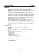
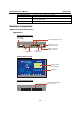
UC-7420/7410 User’s Manual Introduction Operating temperature Storage temperature Regulatory Approvals Warranty -10 to 60°C, (14 to 140°F), 5 to 95% RH -20 to 80°C, (-4 to 185°F), 5 to 95% RH EMC: FCC Class A, CE Class A Safety: UL, CUL, TÜV 5 years Hardware Introduction Appearance and Dimensions Appearance UC-7410/7420 Rear View 12-48 VDC Power Input 10/100 Mbps Ethernet x 2 DC 12-48V PCMCIA LAN1 USB LAN2 Console USB 2.
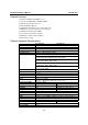
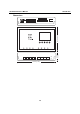
UC-7420/7410 User’s Manual Introduction 44 mm [1.73"] 125 mm [4.92"] Dimensions 197 mm [7.
UC-7420/7410 User’s Manual Introduction Hardware Block Diagram The following block diagram shows the layout of UC-7420’s internal components (the layout for UC-7410 is slightly different).
UC-7420/7410 User’s Manual Introduction Reset-type Buttons UC-7420/7410 has two reset-type buttons. The button labeled Reset has the same effect as unplugging the power and then plugging the power back in. The button labeled Reset to default returns UC-7420/7410 to the factory default parameter configuration. Reset Button Pressing the Reset button initiates a hardware reboot. The button plays the same role as a desktop PC’s reset button. In normal use, you should NOT use the Reset Button.
UC-7420/7410 User’s Manual Introduction Placement Options Wall or Cabinet The two metal brackets that come standard with UC-7420/7410 are used to attach UC-7420/7410 to a wall, or the inside of a cabinet. Use two screws per bracket first to attach the brackets to the bottom of the UC-7420/7410 (Fig. A). Next, use two screws per bracket to attach the UC-7420/7410 to a wall or cabinet (Fig. B).
UC-7420/7410 User’s Manual Introduction DIN-Rail Mounting The aluminum DIN-Rail attachment plate is included in the package. If you need to reattach the DIN-Rail attachment plate to UC-7420/7410, make sure the stiff metal spring is situated towards the top, as shown in the figures below. 1. Insert the top of the DIN-Rail into the slot just below the stiff metal spring. 2. The DIN-Rail attachment unit will snap into place as shown below.
UC-7420/7410 User’s Manual Introduction You should also observe the following common wiring rules: y Use separate paths to route wiring for power and devices. If power wiring and device wiring paths must cross, make sure the wires are perpendicular at the intersection point. NOTE: Do not run signal or communication wiring and power wiring in the same wire conduit. To avoid interference, wires with different signal characteristics should be routed separately.
UC-7420/7410 User’s Manual Introduction Connecting to the Network Connect one end of the Ethernet cable to one of UC-7420/7410’s 10/100M Ethernet ports (8-pin RJ45) and the other end of the cable to the Ethernet network. If the cable is properly connected, UC-7420/7410 will indicate a valid connection to the Ethernet in the following ways: 1 1 The bottom right corner LED indicator maintains a solid green color when the cable is properly connected to a 100 Mbps Ethernet network.
UC-7420/7410 User’s Manual Introduction CompactFlash UC-7420 provides one CompactFlash slot that supports CompactFlash type I/II card expansion. Currently, Moxa provides a CompactFlash disk for plug & play mass storage expansion. You may also use flash disks available from most computer supply outlets. The CompactFlash will be mounted at /mnt/hda If you need device drivers for other kinds of mass storage cards, contact Moxa for information on how to initiate a cooperative development project.
UC-7420/7410 User’s Manual Introduction User AP User Directory (User Configuration) Mini Root File System Configuration Linux Kernel & Root Boot Loader HW To improve system reliability, UC-7420/7410 has a built-in mechanism that prevents the system from crashing. The procedure is as follows. When the Linux kernel boots up, the kernel will mount the root file system, and then enable services and daemons.
UC-7420/7410 User’s Manual Introduction Although JFFS2 is a journaling file system, this does not preclude the loss of data. The file system will remain in a consistent state across power failures and will always be mountable. However, if the board is powered down during a write then the incomplete write will be rolled back on the next boot, but writes that have already been completed will not be affected. Additional information about JFFS2 is available at: http://sources.redhat.com/jffs2/jffs2.
2 Chapter 2 Getting Started In this chapter, we explain how to connect UC-7420/7410, turn on the power, and then get started using the programming and other functions.
UC-7420/7410 User’s Manual Getting Started Powering on UC-7420/7410 Connect the SG wire to the Shielded Contact located in the upper left corner of the UC-7420/7410, and then power on UC-7420/7410 by connecting it to the power adaptor. It takes about 30 to 60 seconds for the system to boot up. Once the system is ready, the Ready LED will light up, and the Network address settings will appear on the LCM display.
UC-7420/7410 User’s Manual Getting Started Telnet Console If you know at least one of the two IP addresses and netmasks, then you can use Telnet to connect to UC-7420/7410’s console utility. The default IP address and Netmask for each of the two ports are given below: Default IP Address Netmask 192.168.3.127 255.255.255.0 LAN 1 192.168.4.127 255.255.255.0 LAN 2 Use a cross-over Ethernet cable to connect directly from your PC to UC-7420/7410.
UC-7420/7410 User’s Manual Getting Started ATTENTION Serial Console Reminder Remember to choose VT100 as the terminal type. Use cable CBL-RJ45F9-150, which comes with UC-7420/7410, to connect to the serial console port. Telnet Reminder When connecting to UC-7420/7410 over a LAN, you must configure your PC’s Ethernet IP address to be on the same subnet as the UC-7420/7410 you wish to contact.
UC-7420/7410 User’s Manual Getting Started Linux Users From a Linux machine, use the “ssh” command to access UC-7420/7410’s Console utility via SSH. #ssh 192.168.3.127 Select yes to complete the connection. [root@bee_notebook root]# ssh 192.168.3.127 The authenticity of host ‘192.168.3.127 (192.168.3.127)’ can’t be established. RSA key fingerprint is 8b:ee:ff:84:41:25:fc:cd:2a:f2:92:8f:cb:1f:6b:2f.
UC-7420/7410 User’s Manual Getting Started Dynamic IP addresses: By default, UC-7420/7410 is configured for “static” IP addresses. To configure one or both LAN ports to request an IP address dynamically, replace static with dhcp and then delete the address, network, netmask, and broadcast lines. Default Setting for LAN1 iface ixp0 inet static address 192.168.3.127 network: 192.168.3.0 netmask 255.255.255.0 broadcast 192.168.3.255 3.
UC-7420/7410 User’s Manual NOTE Getting Started After changing the IP settings, use the networking restart command to activate the new IP address. However, the LCM display will still show the old IP address. To update the LCM display, you will need to reboot the UC-7420/7410. Modifying Network Settings over the Network IP settings can be activated over the network, but the new settings will not be saved to the flash ROM without modifying the file /etc/network/interfaces.
UC-7420/7410 User’s Manual 3. Getting Started Configure the Wireless LAN card’s default SSID setting profile. (Default SSID is “any”) #vi /etc/wlan/wlan.conf // Consult your network administrator for SSID required in your wireless network. For example, SSID_waln0=”any”, Enable_wlan0=y// 4. Duplicate the configuration profile to a new profile. #cp /etc/wlan/wlancfg-DEFAULT /etc/wlan/wlancfg-any // Copy configuration profile “DEFAULT” to new configuration profile “any”// 5.
UC-7420/7410 User’s Manual Getting Started IEEE802.11g The following IEEE802.11g wireless modules are supported: y y y y y y ASUS—WL-107g CNET—CWC-854 (181D version) Edmiax—EW-7108PCg Amigo—AWP-914W GigaByte—GN-WMKG Other brands that use the Ralink RT2500 series chip set To configure the WLAN for IEEE802.11g: 1. Unplug the CardBus Wireless LAN card first. 2. Use the command #vi /etc/networking/interfaces to open the “interfaces” configuration file with vi editor, and then edit the 802.
UC-7420/7410 User’s Manual 3. Getting Started Additional WLAN parameters are contained in the file RT2500STA.dat. To open the file, navigate to the RT2500STA folder and invoke vi, or type the following command #vi /etc/Wireless/RT2500STA/RT2500STA.dat to edit the file with vi editor. Setting options for the various parameters are listed below the figure.
UC-7420/7410 User’s Manual Getting Started NetworkType—Sets the wireless operation mode Setting Explanation Infra Infrastructure mode (uses access points to transmit data) Adhoc Adhoc mode (transmits data from host to host) Channel—Sets the channel Setting Explanation 0 auto 1 to 14 the channel you want to use AuthMode—Sets the authentication mode Setting OPEN SHARED WPAPSK WPANONE EncrypType—Sets encryption type Setting NONE WEP TKIP AES DefaultKeyID—Sets default key ID Setting 1 to 4 Key1Str, Ke
UC-7420/7410 User’s Manual Getting Started TurboRate—Enables or disables TurboRate Setting Explanation 0 disable 1 enable BGProtection—Sets 11b/11g protection (this function is for engineering testing only) Setting Explanation 0 auto 1 always on 2 always off ShortSlot—Enables or disables the short slot time Setting Explanation 0 disable 1 enable TxRate—Sets the TxRate Setting Explanation 0 Auto 1 1 Mbps 2 2 Mbps 3 5.
UC-7420/7410 User’s Manual Getting Started Test Program—Developing Hello.c In this section, we use the standard “Hello” programming example to illustrate how to develop a program for UC-7420/7410. In general, program development involves the following seven steps. Step 1: Connect UC-7420/7410 to a Linux PC. Step 2: Install Tool Chain (GNU Cross Compiler & glibc). Step 3: Set the cross compiler and glibc environment variables. Step 4: Code and compile the program.
UC-7420/7410 User’s Manual Getting Started If there isn’t enough “Available” space for your application, you will need to delete some existing files. To do this, connect your PC to the UC-7420/7410 with the console cable, and then use the console utility to delete the files from UC-7420/7410’s flash memory. NOTE If the flash memory is full, you will need to free up some memory space before saving files to the Flash ROM. Compiling Hello.c The UC-7420/7410 CD contains several example programs.
UC-7420/7410 User’s Manual Getting Started Uploading “Hello” to UC-7420/7410 and Running the Program Use the following command to upload hello-release to the UC-7420/7410 via FTP. 1. From the PC, type: #ftp 192.168.3.127 2. Use bin command to set the transfer mode to Binary mode, and the put command to initiate the file transfer: ftp> bin ftp> put hello-release 3. From the UC-7420/7410, type: # chmod +x hello-release # ./hello-release The word Hello will be printed on the screen. root@Moxa:~# .
UC-7420/7410 User’s Manual Getting Started Compiling tcps2.c The source code for the tcps2 example is located on the CD-ROM at CD-ROM://example/TCPServer2/tcps2.c. Use the following commands to copy the file to a specific directory on your PC. We use the direrctory /home/uc7400/1st_application/. Note that you need to copy 3 files—Makefile, tcps2.c, tcpsp.c—from the CD-ROM to the target directory. #mount –t iso9660 /dev/cdrom /mnt/cdrom #cp /mnt/cdrom/example/TCPServer2/tcps2.
UC-7420/7410 User’s Manual Getting Started Uploading tcps2-release and Running the Program Use the following commands to use FTP to upload tcps2-release to the UC-7420/7410. 1. From the PC, type: #ftp 192.168.3.127 2. Next, use the bin command to set the transfer mode to Binary, and the put command to initiate the file transfer: ftp> bin ftp> put tcps2-release root@server11:/home/uc7400/1st_application [root@server11 1st_application]# ftp 192.168.3.127 Connected to 192.168.3.
UC-7420/7410 User’s Manual 4. Getting Started The program should start running in the background. Use either the #jobs or #ps –ef command to check if the tcps2 program is actually running in the background. #jobs // use this command to check if the program is running 192.168.3.
UC-7420/7410 User’s Manual 158 root 162 root 163 root 169 root 187 root 188 root root@Moxa:~# NOTE Getting Started 1532 3652 2208 2192 1264 1592 S S S S S S /sbin/getty 115200 ttyS1 /usr/sbin/sshd -bash ftpd: 192.168.3.110: root: IDLE ./tcps2-release ps -ef Use the kill -9 command for PID 187 to terminate this program: #kill -9 %187 Testing Procedure Summary 1. 2. 3. 4. 5. 6. 7. 8. 9. Compile tcps2.c (#make). Upload and run tcps2-release in the background (#./tcps2-release &).
UC-7420/7410 User’s Manual NOTE Getting Started The tcps2.c application is a simple example designed to give users a basic understanding of the concepts involved in combining Ethernet communication and serial port communication. However, the example program has some limitations that make it unsuitable for real-life applications. 1. 2. The serial port is in canonical mode and block mode, making it impossible to send data from the Ethernet side to the serial side (i.e.
3 Chapter 3 Managing Embedded Linux This chapter includes information about version control, deployment, updates, and peripherals. The information in this chapter will be particularly useful when you need to run the same application on several UC-7420/7410 units.
UC-7420/7410 User’s Manual Managing Embedded Linux System Version Information To determine the hardware capability of your UC-7420/7410, and what kind of software functions are supported, check the version numbers of your UC-7420/7410’s hardware, kernel, and user file system. Contact Moxa to determine the hardware version. You will need the Production S/N (Serial number), which is located on UC-7420/7410’s bottom label.
UC-7420/7410 User’s Manual Managing Embedded Linux Since different Flash disks have different sizes, it’s a good idea to check the size of your Flash disk before upgrading the firmware, or before using the disk to store your application and data files. Use the #df –h command to list the size of each memory block, and how much free space is available in each block. 192.168.3.127 – PuTTY root@Moxa:~# df -h Filesystem Size Used Available Use% Mounted on /dev/mtdblock3 26.0M 8.9M 17.
UC-7420/7410 User’s Manual Managing Embedded Linux -rw-rw-rw1 ftp ftp 8778996 Nov 29 10:24 UC7420_usrdisk-1.5.frm 226 Transfer complete. ftp> get UC7420-1.5.frm local: UC7420-1.5.frm remote: UC7420-1.5.frm 200 Port command successful. 150 Opening data connection for UC7420-1.5.frm 226 Transfer complete. 13167772 bytes received in 2.17 secs (5925.8 kB/s) ftp> 3. Next, use the upfirm command to upgrade the kernel and root file system: #upfirm uc7400-x.x.x.frm 192.168.3.
UC-7420/7410 User’s Manual Managing Embedded Linux Loading Factory Defaults The easiest way to load factory defaults is to update the firmware (follow the instructions in the previous section to upgrade the firmware). Note that if your user file is not working properly, the system will mount the Mini File System. In this case, you will need to load factory defaults to resume normal operation. Enabling and Disabling Daemons The following daemons are enabled when UC-7420/7410 boots up for the first time.
UC-7420/7410 User’s Manual Managing Embedded Linux Type the command “ps –ef” to list all processes currently running. 192.168.3.
UC-7420/7410 User’s Manual Managing Embedded Linux Next, use the vi open your application program. We use the example program tcps2-release, and put it to run in the background. 192.168.3.127 – PuTTY # !/bin/sh # Add you want to run daemon /root/tcps2-release &~ Then you will find the enabled daemons after you reboot the system. 192.168.3.
UC-7420/7410 User’s Manual Managing Embedded Linux Setting the Run-Level In this section, we outline the steps you should take to set the Linux run-level and execute requests. Use the following command to enable or disable settings: 192.168.3.127 – PuTTY root@Moxa:/ect/rc.d/rc3.d# ls S19nfs-common S25nfs-user-server S99showreadyled S20snmpd S55ssh S24pcmcia S99rmnologin root@Moxa:/etc/rc.d/rc3.d# #cd /etc/rc.d/init.d Edit a shell script to execute /root/tcps2-release and save to tcps2 as an example.
UC-7420/7410 User’s Manual Managing Embedded Linux Adjusting the System Time Setting the Time Manually UC-7420/7410 has two time settings. One is the system time, and the other is the RTC (Real Time Clock) time kept by the UC-7420/7410 hardware. Use the #date command to query the current system time or set a new system time. Use #hwclock to query the current RTC time or set a new RTC time.
UC-7420/7410 User’s Manual Managing Embedded Linux NTP Client UC-7420/7410 has a built-in NTP (Network Time Protocol) client that is used to initialize a time request to a remote NTP server. Use #ntpdate to update the system time. #ntpdate time.stdtime.gov.tw #hwclock –w Visit http://www.ntp.org for more information about NTP and NTP server addresses. 10.120.53.100 – PuTTY root@Moxa:~# date ; hwclock Sat Jan 1 00:00:36 CST 2000 Sat Jan 1 00:00:37 2000 -0.
UC-7420/7410 User’s Manual Managing Embedded Linux Cron—daemon to Execute Scheduled Commands This function is only available for firmware version V1.5 (and later versions). Start Cron from the directory /etc/rc.d/rc.local. It will return immediately, so you don’t need to start it with ‘&’ to run the background. The Cron daemon will search /etc/cron.d/crontab for crontab files, which are named after accounts in /etc/passwd.
UC-7420/7410 User’s Manual Managing Embedded Linux Connecting Peripherals USB Mass Storage This function is only available for firmware version V1.5 (and later versions). The UC-7420/7410 supports PNP (plug-n-play), and hot pluggability for connecting USB mass storage devices. UC-7420/7410 has a built-in auto mount utility that eases the mount procedure.
4 Chapter 4 Managing Communications In this chapter, we explain how to configure UC-7420/7410’s various communication functions.
UC-7420/7410 User’s Manual Managing Communication Telnet / FTP In addition to supporting Telnet client/server and FTP client/server, the UC-7420/7410 system also supports SSH and sftp client/server. To enable or disable the Telnet/ftp server, you first need to edit the file /etc/inetd.conf. Enabling the Telnet/ftp server The following example shows the default content of the file /etc/inetd.conf.
UC-7420/7410 User’s Manual Managing Communication Web Service—Apache The Apache web server’s main configuration file is /etc/apache/httpd.conf, with the default homepage located at /usr/www/html/index.html. Save your own homepage to the following directory: /usr/www/html/ Save your CGI page to the following directory: /usr/www/cgi-bin/ Before you modify the homepage, use a browser (such as Microsoft Internet Explore or Mozilla Firefox) from your PC to test if the Apache Web Server is working.
UC-7420/7410 User’s Manual Managing Communication To open the default CGI test script report page, type http://192.168.3.127/cgi-bin/test-cgi in your browser’s address box. NOTE The CGI function is enabled by default. If you want to disable the function, modify the file /etc/apache/httpd.conf. When you develop your own CGI application, make sure your CGI file is executable. 192.168.3.
UC-7420/7410 User’s Manual Managing Communication Saving a Web Page to the CF Card Since some applications will have web pages that take up a lot of memory space, you will need to be able to run the homepage and other pages from the CF card. In this section, we use a simple example to illustrate how to save web pages to the CF card, and then configure the Apache web server to open the pages. The files used in this example can be downloaded from Moxa’s website.
UC-7420/7410 User’s Manual Managing Communication Step4: Open your browser and connect to the UC-7420/7410 by typing the current LAN1 IP address in the browser’s address box. NOTE Visit the Apache website at http://httpd.apache.org/docs/ for more information about setting up an Apache server. IPTABLES IPTABLES is an administrative tool for setting up, maintaining, and inspecting the Linux kernel’s IP packet filter rule tables.
UC-7420/7410 User’s Manual Managing Communication MASQUERADE—a special form for SNAT. If one host can connect to internet, then other computers that connect to this host can connect to the Internet when it the computer does not have an actual IP address. REDIRECT—a special form of DNAT that re-sends packets to a local host independent of the destination IP address. C. Mangle Table—includes two chains PREROUTING chain—pre-processes packets before the routing process.
UC-7420/7410 User’s Manual Managing Communication UC-7420/7410 supports the following sub-modules. Be sure to use the module that matches your application.
UC-7420/7410 User’s Manual Managing Communication Examples: # iptables -L -n In this example, since we do not use the -t parameter, the system uses the default ‘filter’ table. Three chains are included: INPUT, OUTPUT, and FORWARD. INPUT chains are accepted automatically, and all connections are accepted without being filtered.
UC-7420/7410 User’s Manual Managing Communication Example 2: Accept TCP packets from 192.168.0.1. # iptables –A INPUT –i ixp0 –p tcp –s 192.168.0.1 –j ACCEPT Example 3: Accept TCP packets from Class C network 192.168.1.0/24. # iptables –A INPUT –i ixp0 –p tcp –s 192.168.1.0/24 –j ACCEPT Example 4: Drop TCP packets from 192.168.1.25. # iptables –A INPUT –i ixp0 –p tcp –s 192.168.1.25 –j DROP Example 5: Drop TCP packets addressed for port 21.
UC-7420/7410 User’s Manual 1. #ehco 1 > 2. #modprobe 3. #modprobe 4. #modprobe 5. #iptables or 6. #iptables Managing Communication /proc/sys/net/ipv4/ip_forward iptable_nat ip_conntract ipt_MASQUERADE -t nat –A POSTROUTING –o ixp0 –j SNAT --to-source 192.168.3.127 –t nat –A POSTROUTING –o ixp0 –j MASQUERADE Enabling NAT at Bootup In the most of real world situations, you will want to use a simple shell script to enable NAT when UC-7420/7410 boots up. The following script is an example.
UC-7420/7410 User’s Manual NOTE Managing Communication Click on the following links for more information about ppp: http://tldp.org/HOWTO/PPP-HOWTO/index.html http://axion.physics.ubc.ca/ppp-linux.html The pppd daemon is used to connect to a PPP server from a Linux system. For detailed information about pppd see the man page. Example 1: Connecting to a PPP server over a simple dial-up connection The following command is used to connect to a PPP server by modem.
UC-7420/7410 User’s Manual Managing Communication crtscts Use hardware flow control between computer and modem (at 115200 this is a must). modem Indicates that this is a modem device; pppd will hang up the phone before and after making the call. defaultroute Once the PPP link is established, make it the default route; if you have a PPP link to the Internet, this is probably what you want. 192.1.1.17 This is a degenerate case of a general option of the form x.x.x.x:y.y.y.y. Here x.x.x.
UC-7420/7410 User’s Manual Managing Communication where z.z.z.z is the address of your name server. This should work. Here’s what the response could look like: waddington:~$p ping 129.67.1.165 PING 129.67.1.165 (129.67.1.165): 56 data bytes 64 bytes from 129.67.1.165: icmp_seq=0 ttl=225 time=268 ms 64 bytes from 129.67.1.165: icmp_seq=1 ttl=225 time=247 ms 64 bytes from 129.67.1.165: icmp_seq=2 ttl=225 time=266 ms ^C --- 129.67.1.
UC-7420/7410 User’s Manual Managing Communication PPPoE How to use PPPoE on UC-7408: 1. Update two files: /usr/sbin/pppd and /usr/lib/pppd/2.4.1/pppoe.so on the target UC-7408 for version V1.5 or earlier versions. Copy the files from the web or CD-ROM, and directly update it by the copy command or FTP. 2. Connect UC-7408’s LAN port to an ADSL modem with a cross-over cable, HUB, or switch. 3. Login to the UC-7408 as the root user. 4.
UC-7420/7410 User’s Manual 5. Managing Communication Edit the file /etc/ppp/pap-secrets and add the following: “username@hinet.net” * “password” * “username@hinet.net” is the username obtained from the ISP to log in to the ISP account. “password” is the corresponding password for the account. 6.
UC-7420/7410 User’s Manual 7. Managing Communication Add one of two files: /etc/ppp/options.ixp0 or /etc/ppp/options.ixp1. The choice depends on which LAN is connected to the ADSL modem. If you use LAN1 to connect to the ADSL modem, then add /etc/ppp/options.ixp0. If you use LAN2 to connect to the ADSL modem, then add /etc/ppp/options.ixp1. The file context is shown below: Type your username (the one you set in the /etc/ppp/pap-secrets and /etc/ppp/chap-secrets files) after the “name” option.
UC-7420/7410 User’s Manual Managing Communication NFS (Network File System) The Network File System (NFS) is used to mount a disk partition on a remote machine, as if it were on a local hard drive, allowing fast, seamless sharing of files across a network. NFS allows users to develop applications for UC-7420/7410, without worrying about the amount of disk space that will be available. UC-7420/7410 supports NFS protocol for both client and server.
UC-7420/7410 User’s Manual Managing Communication async The async option instructs the server to lie to the client, telling the client that all data has been written to the stable storage. Example 1 /tmp *(rw,no_root_squash) In this example, UC-7420/7410 shares the /tmp directory to everyone, gives everyone both read and write authority. The root user on the client machine will have the same level of access to files on the system as the root on the server. Example 2 /home/public 192.168.0.
UC-7420/7410 User’s Manual NOTE Managing Communication Click on the following link for more information about smtpclient: http://www.engelschall.com/sw/smtpclient/ To send an email message, use the ‘smtpclient’ utility, which uses SMTP protocol. Type #smtpclient –help to see the help message. Example: smtpclient –s test –f sender@company.com < mail-body-message -s: -f: -S: –S IP_address receiver@company.com The mail subject.
UC-7420/7410 User’s Manual Managing Communication ***** SNMP QUERY FINISHED ***** NOTE Click on the following links for more information about MIB II and RS-232 like group: http://www.faqs.org/rfcs/rfc1213.html http://www.faqs.org/rfcs/rfc1317.html Æ UC-7420/7410 does NOT support SNMP trap. The following tables list the variables supported by UC-7420/7410. Open VPN This function is only available for firmware version V1.5 (and later versions).
UC-7420/7410 User’s Manual 2. Managing Communication Generate a preset shared key by typing the command: # openvpn --genkey --secret secrouter.key Copy the file that is generated to the OpenVPN machine. 3. Generate a script file named openvpn-bridge on each OpenVPN machine. This script reconfigures interface “ixp1” as IP-less, creates logical bridge(s) and TAP interfaces, loads modules, enables IP forwarding, etc.
UC-7420/7410 User’s Manual Managing Communication IFS=$oIFS if [ “$FOUND” = “no” ]; then modprobe $mname fi } start() { ifcfg_vpn if [ ! \( -d “/dev/net” \) ]; then mkdir /dev/net fi if [ ! \( -r “/dev/net/tun” \) ]; then # create a device file if there is none mknod /dev/net/tun c 10 200 fi # load modules “tun” and “bridge” mname=tun module_up mname=bridge module_up # create an ethernet bridge to connect tap devices, internal interface brctl addbr br0 brctl addif br0 $iface # the bridge receives data fro
UC-7420/7410 User’s Manual Managing Communication openvpn --rmtun --dev tap${i} i=`expr $i + 1` if [ $i -ge $maxtap ]; then break fi done brctl delif br0 $iface brctl delbr br0 ifconfig br0 down ifconfig $iface $IPADDR netmask $NETMASK broadcast $BROADCAST killall -TERM openvpn } case “$1” in start) start ;; stop) stop ;; restart) stop start ;; *) echo “Usage: $0 [start|stop|restart]” exit 1 esac exit 0 #---------------------------------- end ----------------------------- Create link symbols to enable th
UC-7420/7410 User’s Manual Managing Communication up /etc/openvpn/B-tap0-br.sh #---------------------------------- Start---------------------------#!/bin/sh # value after “-net” is the subnet behind the remote peer route add -net 192.168.2.0 netmask 255.255.255.0 dev br0 #---------------------------------- end ----------------------------- Note: Select cipher and authentication algorithms by specifying “cipher” and “auth”.
UC-7420/7410 User’s Manual Managing Communication Setup 2: Ethernet Bridging for Private Networks on the Same Subnet 1. Set up four machines as shown in the following diagram: Host A local net OpenVPN A eth1: 192.168.2.173 eth0: 192.168.2.171 Internet eth0: 192.168.8.173 ixp0: 192.168.8.174 eth0: 192.168.2.172 ixp1: 192.168.2.174 Host B 2. OpenVPN B local net The configuration procedure is almost the same as for the previous example.
UC-7420/7410 User’s Manual 2. Managing Communication Create a configuration file named “A-tun.conf” and an executable script file named “A-tun.sh”. # point to the peer remote 192.168.8.174 dev tun secret /etc/openvpn/secrouter.key cipher DES-EDE3-CBC auth MD5 tun-mtu 1500 tun-mtu-extra 64 ping 40 ifconfig 192.168.2.173 192.168.4.174 up /etc/openvpn/A-tun.sh #--------------------------------#!/bin/sh # value after “-net” is the subnet route add -net 192.168.4.
5 Chapter 5 Programmer’s Guide This chapter includes important information for programmers.
UC-7420/7410 User’s Manual Programmer’s Guide Flash Memory Map Partition sizes are hard coded into the kernel binary. To change the partition sizes, you will need to rebuild the kernel. The flash memory map is shown in the following table.
UC-7420/7410 User’s Manual Programmer’s Guide Obtaining help Use the Linux man utility to obtain help on many of the utilities provided by the tool chain. For example to get help on the armv5b-linux-gcc compiler, issue the command: #man armv5b-linux-gcc Cross Compiling Applications and Libraries To compile a simple C application, just use the cross compiler instead of the regular compiler: #mxscaleb-gcc –o example –Wall –g –O2 example.
UC-7420/7410 User’s Manual Programmer’s Guide Debugging with GDB First compile the program must with option -ggdb. Use the following steps: 1. To debug a program called hello-debug on the target, use the command: #gdbserver 192.168.4.142:2000 hello-debug This is where 2000 is the network port number on which the server waits for a connection from the client. This can be any available port number on the target.
UC-7420/7410 User’s Manual Programmer’s Guide Buzzer The device node is located at /dev/console. UC-7420/7410 supports Linux standard buzzer control, with UC-7420/7410’s buzzer running at a fixed frequency of 100 Hz. You must include . 1. Function: KDMKTONE ioctl(fd, KDMKTONE, unsigned int arg); Description: The buzzer’s behavior is determined by the argument arg. The “high word” part of arg gives the length of time the buzzer will sound, and the “low word” part gives the frequency.
UC-7420/7410 User’s Manual Programmer’s Guide int swtd_enable(int fd, unsigned long time) Description Enable application sWatchDog. And you must do ack after this process. Input int fd - the file handle, from the swtd_open() return value. unsigned long time - The time you wish to ack sWatchDog periodically. You must ack the sWatchDog before timeout. If you do not ack, the system will be reboot automatically. The minimal time is 50 msec, the maximum time is 60 seconds. The time unit is msec.
UC-7420/7410 User’s Manual Programmer’s Guide int swtd_ack(int fd) Description: Acknowledge sWatchDog. When the user application enable sWatchDog. It need to call this function periodically with user predefined time in the application program. Input : int fd - the file handle from swtd_open() return value. Output: OK will be zero. The other has some error, to get error code from errno(). int swtd_close(int fd) Description: Close the file handle.
UC-7420/7410 User’s Manual Programmer’s Guide swtd_close(fd); exit(0); } The makefile is shown below: all: mxscaleb-gcc –o xxxx xxxx.c –lmoxalib Example 2: #include #include #include #include #include #include #include #include #include static void mydelay(unsigned long msec) { struct timeval time; time.tv_sec = msec / 1000; time.
UC-7420/7410 User’s Manual Programmer’s Guide exit(1); } The makefile is shown below: all: mxscaleb-gcc –o xxxx xxxx.c –lmoxalib UART The normal tty device node is located at /dev/ttyM0 … ttyM7, and the modem tty device node is located at /dev/cum0 … cum7. UC-7420/7410 supports Linux standard termios control. The Moxa UART Device API allows you to configure ttyM0 to ttyM7 as RS-232, RS-422, 4-wire RS-485, or 2-wire RS-485. UC-7420/7410 supports RS-232, RS-422, 2-wire RS-485, and 4-wire RS485.
UC-7420/7410 User’s Manual Programmer’s Guide Example to get the baud rate #include #include struct termios term; int fd, speed; fd = open(“/dev/ttyM0”, O_RDWR); tcgetattr(fd, &term); if ( (term.c_cflag & (CBAUD|CBAUDEX)) != B4000000 ) { // follow the standard termios baud rate define } else { ioctl(fd, MOXA_GET_SPECIAL_BAUD_RATE, &speed); } Baud rate inaccuracy Divisor = 921600/Target Baud Rate.
UC-7420/7410 User’s Manual Programmer’s Guide KeyPad The device node is /dev/keypad. The key value is defined in moxadevice.h. int ioctl(fd, IOCTL_KEYPAD_HAS_PRESS, int *flag); Checks how many keys have been pressed. Argument 3 returns the number of pressed keys. 0 means no keys were pressed. int ioctl(fd, IOCTL_KEYPAD_GET_KEY, int *key); Gets the value of the last key that was pressed. This functions only reads one key value for each function call. The value of the key value is returned in argument 3.
A Appendix A System Commands Linux normal command utility collection File manager 1. 2. 3. 4. 5. 6. 7. 8. 9. 10. 11. 12. 13. 14.
UC-7420/7410 User’s Manual System Commands Process 1. 2. kill ps kill process display now running process 1. 2. 3. 4. 5. 6. 7. 8. 9. 10. 11. 12. 13. dmesg sty zcat mknod free date env clear reboot halt du gzip, gunzip hostname dump kernel log message to set serial port dump .