UC-8410/8416/8418 Hardware User’s Manual Second Edition, September 2009 www.moxa.com/product © 2009 Moxa Inc. All rights reserved. Reproduction without permission is prohibited.
UC-8410/8416/8418 Hardware User’s Manual The hardware described in this manual is furnished under a license agreement and may be used only in accordance with the terms of that agreement. Copyright Notice Copyright © 2009 Moxa Inc. All rights reserved. Reproduction without permission is prohibited. Trademarks MOXA is a registered trademark of Moxa Inc. All other trademarks or registered marks in this manual belong to their respective manufacturers.
Table of Contents Chapter 1 Introduction ..................................................................................................1-1 Overview.................................................................................................................................. 1-2 Package Checklist .................................................................................................................... 1-2 Product Features .....................................................................
1 Chapter 1 Introduction Thank you for purchasing the Moxa UC-8410/8416/8418 RISC-based ready-to-run embedded computer. The UC-8410/8416/8418 feature 8 RS-232/422/485 serial ports, 3 10/100 Mbps Ethernet ports, digital input and digital output channels, switching ports, and CompactFlash and USB ports for adding additional memory. All of these features make the UC-8410/8416/8418 ideal for your embedded applications. This manual introduces the hardware of the UC-8410/8416/8418 embedded computers.
UC-8410/8416/8418 Hardware User’s Manual Introduction Overview The UC-8410/8416/8418 features 8 RS-232/422/485 serial ports, 3 10/100 Mbps Ethernet ports, 4 digital input channels and 4 digital output channels (12 digital input channels and 12 digital output channels for the UC-8418), 8 10/100 Mbps switch ports (UC-8416 only), a CompactFlash slot for flash disk expansion, and 2 USB ports for adding additional memory (such as a USB flash drive).
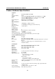
UC-8410/8416/8418 Hardware User’s Manual Introduction Product Hardware Specifications Computer CPU: OS (pre-installed): DRAM: Flash: Intel XScale IXP435 533 MHz Linux Onboard 256 MB DDR2 SDRAM, support DDR2 up to 512 MB Onboard 16 MB NOR Flash to store OS, suport up to 32 MB Onboard 32 MB NAND flash to store data Full function CompactFlash x 1 USB 2.
UC-8410/8416/8418 Hardware User’s Manual Connector Type: Isolation: LEDs System: LAN: Serial: Physical Characteristics Housing: Weight: Dimensions: Introduction 10-pin screw terminal block (4 points, GND) 3 KV optical isolation Power x 1, Ready x 1, Storage x 1, Battery for SRAM x 1 10M/100M x 2 TxD, RxD (8 of each) SECC sheet metal (1 mm) UC-8410: 850 g UC-8416: 930 g UC-8418: 1 kg UC-8410: 200 x 36.5 x 120 mm (7.87 x 1.44 x 4.72 in) UC-8416/8418: 200 x 56.5 x 120 mm (7.87 x 2.20 x 4.
2 Chapter 2 Appearance and Dimensions The following topics are covered in this chapter: Appearance Dimensions Hardware Block Diagrams LED Indicators Reset Button Real Time Clock
UC-8410/8416/8418 Hardware User’s Manual Appearance and Dimensions Appearance UC-8410 Rear View LED Indicators (Power, SRAM Battery, Ready, Storage) DI Channel x 4 10/100 Mbps Ethernet x 3 DO Channel x 4 UC-8410 Top View UC-8410 Front View Reset Button USB 2.
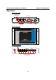
UC-8410/8416/8418 Hardware User’s Manual Appearance and Dimensions UC-8416 Rear View 10/100 Mbps Ethernet Switch Port x 8 LED Indicators (Power, SRAM Battery, 10/100 Mbps Ready, Storage) Ethernet x 3 DI Channel x 4 DO Channel x 4 UC-8416 Top View UC-8416 UC-8416 Front View Reset Button USB 2.
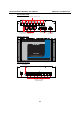
UC-8410/8416/8418 Hardware User’s Manual Appearance and Dimensions UC-8418 Rear View DI Channel x 8 LED Indicators DO Channels x 8 (Power, SRAM Battery, 10/100 Mbps Ready, Storage) Ethernet x 3 DI Channel x 4 DO Channel x 4 Power Input 12 to 48 VDC UC-8418 Top View UC-8418 UC-8418 Front View Reset Button CANbus Port x 2 DB9 USB 2.
UC-8410/8416/8418 Hardware User’s Manual Appearance and Dimensions Dimensions 120 mm UC-8410 36.5 mm 200 mm (Unit=mm) 2-5 45.
UC-8410/8416/8418 Hardware User’s Manual Appearance and Dimensions 70 25.10 120.20 UC-8416 200 214 59.50 56.
UC-8410/8416/8418 Hardware User’s Manual Appearance and Dimensions 70 25.10 120.20 UC-8418 200 214 59.50 56.
UC-8410/8416/8418 Hardware User’s Manual Appearance and Dimensions Hardware Block Diagrams The following block diagram shows the layout of the UC-8410/8416/8418’s internal components.
UC-8410/8416/8418 Hardware User’s Manual Appearance and Dimensions UC-8418 D/I x 8 D/O x 8 CAN Port x 2 D/I CAN 1 CAN 2 D/O CANbus Controller USB x 2 LAN3 CF Ethernet Controller IC CF Card Controller PCI 104 Slot USB Hosts Ethernet x 2 Console LAN2 LAN1 RS-232 Ethernet x 1 PHY 2 3 4 Power circuit RTC Decoder Moxa UART ASIC 1 PHY XScale IXP435 533 MHz 256 MB DDR2 16 MB NOR Flash 32 MB NAND Flash PCI Bus PCI Bus Power 5 6 7 8 D/I x 4 D/O x 4 RS-232/422/485 x 8 LED Indicato
UC-8410/8416/8418 Hardware User’s Manual Appearance and Dimensions Reset Button The button labeled Reset returns the UC-8410/8416/8418 to its factory default configuration. Press the Reset button continuously for at least 5 seconds to load the factory default configuration. After the factory default configuration has been loaded, the system will reboot automatically. The Ready LED will blink on and off for the first 5 seconds, and then maintain a steady glow once the system has rebooted.
3 Chapter 3 The following topics are covered in this chapter: Wall or Cabinet Mounting DIN-Rail Mounting Mounting Options
UC-8410/8416/8418 Hardware User’s Manual Mounting Options Wall or Cabinet Mounting The two metal brackets that come standard with the UC-8410/8416/8418 are used to attach the UC-8410/8416/8418 to a wall or the inside of a cabinet. First, use two screws per bracket to attach the brackets to the bottom of the UC-8410/8416/8418 (Fig. A). Next, use two screws per bracket to attach the UC-8410/8416/8418 to a wall or cabinet (Fig. B).
UC-8410/8416/8418 Hardware User’s Manual Mounting Options DIN-Rail Mounting An aluminum DIN-Rail attachment plate is included with the product. If you need to reattach the DIN-Rail attachment plate to the UC-8410/8416/8418, make sure the stiff metal spring is situated towards the top, as shown in the following figures. STEP 1: Insert the top of the DIN-Rail into the slot just below the stiff metal spring. STEP 2: The DIN-Rail attachment unit will snap into place as shown below.
4 Chapter 4 Hardware Connection Description This section describes how to connect the UC-8410/8416/8418 to serial devices for first time testing purposes.
UC-8410/8416/8418 Hardware User’s Manual Hardware Connection Description Wiring Requirements ATTENTION Safety First! Be sure to disconnect the power cord before installing and/or wiring your UC-8410/8416/8418. Wiring Caution! Calculate the maximum possible current in each power wire and common wire. Observe all electrical codes dictating the maximum current allowable for each wire size. If the current goes above the maximum ratings, the wiring could overheat, causing serious damage to your equipment.
UC-8410/8416/8418 Hardware User’s Manual Hardware Connection Description Grounding the UC-8410/8416/8418 Grounding and wire routing help limit the effects of noise due to electromagnetic interference (EMI). Run the ground connection from the ground screw to the grounding surface prior to connecting devices. ATTENTION This product is intended to be mounted to a well-grounded mounting surface, such as a metal panel.
UC-8410/8416/8418 Hardware User’s Manual 8 1 Hardware Connection Description The UC-8416 has 8 10/100 Mbps switch ports. The LED indicators and pin assignments are exactly the same as the Ethernet ports. Connecting to a Serial Device Use properly wired serial cables to connect the UC-8410/8416/8418 to serial devices. The UC-8410/8416/8418’s serial ports (P1 to P8) use 8-pin RJ45 connectors. The ports can be configured by software for RS-232, RS-422, or 2-wire RS-485.
UC-8410/8416/8418 Hardware User’s Manual Hardware Connection Description Connecting to the Console Port The UC-8410/8416/8418’s console port is a 4-pin pin header RS-232 port. Refer to the following figure for console port cable pin assignments. Serial console Port&Pinouts Pin 1 2 3 4 Serial Console Cable Signal TxD RxD NC GND The console port is located blow the CF card socket. Use a screwdriver to remove the two screws holding the cover to the embedded computer’s housing.
UC-8410/8416/8418 Hardware User’s Manual Hardware Connection Description CompactFlash The UC-8410/8416/8418 provides one CompactFlash slot that supports CompactFlash type I/II card expansion. Currently, Moxa provides a CompactFlash card for storage expansion. Be sure of power off the computer before inserting or removing the CompactFlash card. See the following description for CompactFlash card installation instructions. The CF cover is located on the back of the UC-8410/8416/8418.
UC-8410/8416/8418 Hardware User’s Manual Hardware Connection Description If you need device drivers for other kinds of mass storage cards, contact Moxa for information on how to initiate a cooperative development project. USB The UC-8410/8416/8418 provides two USB 2.0 hosts. The USB hosts now support adding USB storage devices. DI/DO The UC-8410 and UC-8416 have 4-ch digital outputs and 4-ch digital inputs, while the UC-8418 has 12-ch digital inputs and 12-ch digital outputs.
UC-8410/8416/8418 Hardware User’s Manual Hardware Connection Description Wet Contact Note: If are using wet contacts, you must connect “COM” to power.
A Appendix A Regulatory Approval Statements This device complies with part 15 of the FCC Rules. Operation is subject to the following two conditions: (1) This device may not cause harmful interference, and (2) this device must accept any interference received, including interference that may cause undesired operation.