
User`s manual

UC-8410/8416/8418 Hardware User’s Manual Appearance and Dimensions
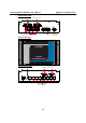
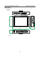
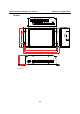
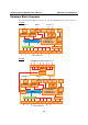
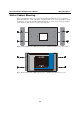
Hardware Block Diagrams
The following block diagram shows the layout of the UC-8410/8416/8418’s internal components.
UC-8410
Ethernet x 2Ethernet x 1 USB x 2
Console
PHYPHY
PCI Bus
RTC
Decoder
1
2 3 4 5 6 7 8
Moxa UART ASIC
USB
Hosts
XScale IXP-435 533 MHz
16 MB NOR Flash
32 MB NAND Flash
256 MB DDR2
232-SR
Power
Power
circuit
RS-232/422/485 x 8
LAN2
LAN1
D/I x 4 D/O x 4
PCI Bus
CF Card
Controller
Ethernet
Controller IC
CF
LAN3
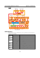
UC-8416
Console
PHYPHY
PCI Bus
RTC
Decoder
1
2 3 4 5 6 7 8
Moxa UART ASIC
USB
Hosts
XScale IXP435 533 MHz
16 MB NOR Flash
32 MB NAND Flash
256 MB DDR2
232-SR
Power
Power
circuit
RS-232/422/485 x 8
Ethernet x 2
LAN2 LAN1
D/I x 4 D/O x 4
PCI Bus
CF Card
Controller
Ethernet
Controller IC
Ethernet x 1 USB x 2
CF
1
2 3 4 5 6 7 8
LAN3
Ethernet
Controller IC
10/100 Mbps Unmanaged Switch Port x 8
Switch IC
PCI 104
Slot
2-8