
User`s manual
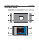

UC-8410/8416/8418 Hardware User’s Manual Appearance and Dimensions
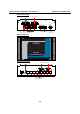
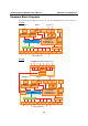
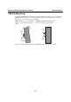
UC-8418
Console
PHYPHY
PCI Bus
RTC
Decoder
1
2 3 4 5 6 7 8
Moxa UART ASIC
USB
Hosts
XScale IXP435 533 MHz
16 MB NOR Flash
32 MB NAND Flash
256 MB DDR2
232-SR
Power
Power
circuit
RS-232/422/485 x 8
Ethernet x 2
LAN2 LAN1
D/I x 4 D/O x 4
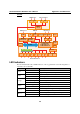
PCI Bus
CF Card
Controller
Ethernet
Controller IC
Ethernet x 1 USB x 2
CF
LAN3
CANbus
Controller
D/I D/O
CAN 1 CAN 2
CAN Port x 2
D/O x 8D/I x 8
PCI 104
Slot
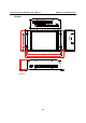
LED Indicators
The UC-8410/8416/8418 has 14 LED indicators on the top panel. Refer to the following table for
information about each LED.
LED Name Color Meaning
Green Power is on.
Power
Off No power input or any other power error.
Green System is ready.
Ready
Off OS boot up failure or other system initialization error.
Yellow (not blinking) CF card inserted.
Yellow (blinking) Data is being read or written.
Storage
Off No CF card inserted.
Red (blinking) Battery is recharging.
Battery
Off Battery is normal.
Green Data is being sent through the serial port.
TX 1-8
Off Data is not being transmitted.
Yellow Data is being received through the serial port.
RX 1-8
Off Data is not being received.
2-9