
User`s manual


UC-8410/8416/8418 Hardware User’s Manual Hardware Connection Description
8 1
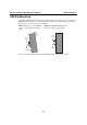
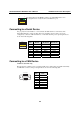
The UC-8416 has 8 10/100 Mbps switch ports. The LED indicators and
pin assignments are exactly the same as the Ethernet ports.
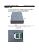
Connecting to a Serial Device
Use properly wired serial cables to connect the UC-8410/8416/8418 to serial devices. The
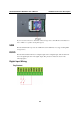
UC-8410/8416/8418’s serial ports (P1 to P8) use 8-pin RJ45 connectors. The ports can be
configured by software for RS-232, RS-422, or 2-wire RS-485. The precise pin assignments are
shown in the following table:
8 1
Pin RS-232
RS-422/
RS-485-4w
RS-485-2w
1 DSR --- ---
2 RTS TXD+ ---
3 GND GND GND
4 TXD TXD- ---
5 RXD RXD+ Data+
6 DCD RXD- Data-
7 CTS --- ---
8 DTR --- ---
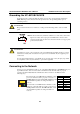
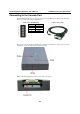
Connecting to a CAN Device
CAN Ports (UC-8418 only)
The UC-8418 has 2 CAN ports for connecting CAN devices. The CAN ports (CAN1 and CAN2)
use DB9 male connectors. The pin assignments are shown in the following table:
54321
9876
Pin CAN
1---
2CAN-L
3---
4---
5---
6---
7CAN-H
8 ---
4-4