
User's Manual


UC-8100A-ME-T Series Hardware Hardware Connection Description
3-2
ATTENTION
Safety First!
Be sure to disconnect the power cord before doing installations and/or wiring.
Electrical Current Caution!
Calculate the maximum possible current in each power wire and common wire. Observe all electrical codes
dictating the maximum current allowable for each wire size.
If the current goes above the maximum ratings, the wiring could overheat, causing serious damage to your
equipment.
Temperature Caution!
Be careful when handling the unit. When the unit is plugged in, the internal components generate heat, and
consequently the outer casing may feel hot to the touch.
ATTENTION
A shielded power cord is required to meet FCC emission limits and also to prevent interference with nearby
radio and television reception. It is essential that only the supplied power cord be used.
You are cautioned that changes or modifications not expressly approved by the party responsible for
compliance could void your authority to operate the equipment.
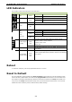
Wiring Requirements
In this section, we describe how to connect various devices to the embedded computer. Be sure to read and
follow these common safety precautions before proceeding with the installation of any electronic device:
•
Use separate paths to route wiring for power and devices. If power wiring and device wiring paths must
cross, make sure the wires are perpendicular at the intersection point.
NOTE Do not run signal or communication wiring and power wiring in the same wire conduit. To avoid interference,
wires with different signal characteristics should be routed separately.
•
You can use the type of signal transmitted through a wire to determine which wires should be kept separate.
The rule of thumb is that wiring that shares similar electrical characteristics can be bundled together.
•
Keep input wiring and output wiring separate.
•
When necessary, it is strongly advised that you label wiring to all devices in the system.
Connecting the Power
Terminal Block
Connect the 12 to 36 VDC power line to the terminal block, which is connector to the
UC-8100A-ME-T Series computer. If the power is supplied properly, the “Power” LED will
glow a solid green light. The power input location and pin definition are shown in the
adjacent diagram.
SG: The Shielded Ground (sometimes called Protected Ground) contact is the top contact of
the 3-pin power terminal block connector when viewed from the angle shown here. Connect
the SG wire to an appropriate grounded metal surface.
Grounding the Unit
There is another grounding connector on the top panel of the computer. Use this connector to connect a
well-grounded mounting surface, such as a metal panel