
User's Manual


UC-8100A-ME-T Series Hardware Hardware Connection Description
3-3
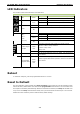
Pin Signal
1
Tx+
2
Tx-
3
Rx+
4 –
5 –
6
Rx-
7 –
8 –
Pin RS-232 RS-422 RS-485
1
TXD TXD+
–
2
RXD TXD-
–
3
RTS RXD+ D+
4
CTS RXD- D-
5
GND GND GND
Connecting to the Network
The Ethernet ports are located on the front panel of the UC-8100A-ME-T computers. The pin assignments for
the Ethernet port are shown in the following figure. If you are using your own cable, make sure that the pin
assignments on the Ethernet cable connector match the pin assignments on the Ethernet port.
Connecting to a USB Device
The UC-8100A-ME-T Series computers come with a USB port located at the lower part of the front panel,
allowing users to connect to a device with an USB interface. The USB port uses a type A connector. By default,
the USB storage is mounted at /mnt/usbstorage.
Connecting to Serial Ports
The two serial ports (P1 and P2) use terminal connectors. Each port can be configured by software for RS-232,
RS-422, or RS-485. The pin assignments for the ports are shown in the following table:
Inserting the SD Card and SIM Card
The UC-8100A-ME-T comes with an SD socket for storage expansion, and a SIM card socket for cellular
communication. The SD card/SIM card sockets are located at the lower part on the front panel. To install the
cards, remove the screw and the protection cover to access the sockets, and then insert the SD card or the SIM
card into the sockets directly. You will hear a click when the cards are in place. To remove the cards, push the
cards in before releasing them.