
User Manual


You should also pay attention to the following items:
Use separate paths to route wiring for power and devices. If power wiring and
device wiring paths must cross, make sure the wires are perpendicular at the
intersection point.
NOTE: Do not run signal or communication wiring and power wiring in the
same wire conduit. To avoid interference, wires with different signal
characteristics should be routed separately.
You can use the type of signal transmitted through a wire to determine which
wires should be kept separate. The rule of thumb is that wiring that shares
similar electrical characteristics can be bundled together.
Keep input wiring and output wiring separate.
Where necessary, it is strongly advised that you label wiring to all devices in the system
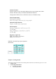
Connecting the Power
Connect the 12-48 VDC power line with NPort W2250/2150’s terminal block. If the power is properly
supplied, the “Ready” LED will show a solid red color until the system is ready, at which time the
“Ready” LED will change to a green color.
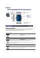
Connecting to the Network
Connect one end of the Ethernet cable to NPort W2250/2150’s 10/100M Ethernet port and
the other end of the cable to the Ethernet network. If the cable is properly connected, NPort
W2250/2150 will indicate a valid connection to the Ethernet in the following ways:
The Ethernet LED maintains a solid green color when connected to a 100
Mbps Ethernet network.
The Ethernet LED maintains a solid orange color when connected to a 10
Mbps Ethernet network.
The Ethernet LED will flash when Ethernet packets are being transmitted or
received.
Connecting to a Serial Device
Connect the serial data cable between NPort W2250/2150 and the serial device. Serial data
cables are optional accessories for NPort W2250/2150. Refer to Chapter 1 under Optional
Accessories for information on the RJ45-to-DB25 and RJ45-to-DB9 cables.
LED Indicators
Type Color Meaning