
User's Manual


UC-7112/7110 User’s Manual UC Finder
3-3
and serial COM terminal.
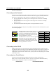
Connecting to the Network
Connect one end of the Ethernet cable to ThinkCore W341/321/311’s 10/100M Ethernet port and
the other end of the cable to the Ethernet network. If the cable is properly connected, ThinkCore
W341/321/311 will indicate a valid connection to the Ethernet in the following ways:
y The top-right LED on the connector glows a solid green when connected to a 100 Mbps
Ethernet network.
y The top-left LED on the connector glows a solid orange when connected to a 10 Mbps
Ethernet network.
y The LEDs will flash when Ethernet packets are being transmitted or received.
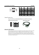
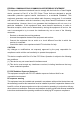
The 10/100 Mbps Ethernet LAN port use 8-pin RJ45 connectors. Pinouts for these ports are given
in the following diagram.
18
The LED indicator in the lower right corner glows
a solid green color when the cable is properly
connected to a 100 Mbps Ethernet network. The
LED will flash on and off when Ethernet packets
are being transmitted or received.
18
The LED indicator in the lower left corner glows a
solid orange color when the cable is properly
connected to a 10 Mbps Ethernet network. The
LED will flash on and off when Ethernet packets
are being transmitted or received.
Pin Signal
1 ETx+
2 ETx-
3 ERx+
4 ---
5 ---
6 ERx-
7 ---
8 ---
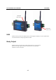
Connecting to the WLAN
ThinkCore W341/321/311 is the WLAN ready wireless embedded computer, embeds an 802.11
a/b/g WLAN module inside and support the WEP, WPA and WPA2 data encryption. To make sure
the WLAN function works normally, please enter the system first to do the associated WLAN
configuration via fixed network or serial console, you may refer to the OS operating user’s manual
for the further detail.
Connecting to a Serial Device
Connect the serial cable between ThinkCore W341/321/311 and the serial device(s).
Serial ports P1 to P4 use male DB9 connectors, and can be configured for RS-232/422/485 by
software. The pin assignments are shown in the following table:
DB9 Male Port
RS-232/422/485 Pinouts