W311/321/341 Hardware User’s Manual Sixth Edition, March 2009 www.moxa.com/product © 2009 Moxa Inc. All rights reserved. Reproduction without permission is prohibited.
W311/321/341 Hardware User’s Manual The hardware described in this manual is furnished under a license agreement and may be used only in accordance with the terms of that agreement. Copyright Notice Copyright © 2009 Moxa Inc. All rights reserved. Reproduction without permission is prohibited. Trademarks MOXA is a registered trademark of Moxa Inc. All other trademarks or registered marks in this manual belong to their respective manufacturers.
Table of Contents Chapter 1 Introduction ..................................................................................................1-1 Overview.................................................................................................................................. 1-2 Package Checklist .................................................................................................................... 1-2 Product Features .....................................................................
1 Chapt er 1 I nt roduc t ion The W300 series is a line of wireless RISC-based embedded computers that features 802.11a/b/g WLAN, RS-232/422/485 serial ports, and an Ethernet port in a small, rugged chassis. In addition, all models feature an SD slot, and the W341 features two USB 2.0 hosts and one relay output channel. Your W300 series embedded computer is ideal for diverse, machine-to-machine embedded applications. It enables wireless operation for traditionally wired networks and serial devices.
W311/321/341 Hardware User’s Manual Introduction Overview The W300 Series wireless embedded computer is designed around the Moxa ART ARM9 32-bit RISC processor. Unlike the X86 CPU, which uses a CISC design, the Moxa ART ARM9 uses RISC architecture and modern semiconductor technology to provide a powerful computing engine without generating significant heat.
W311/321/341 Hardware User’s Manual Introduction Product Features W300 Series computers have the following features: y Moxa ART 32-bit ARM9 industrial communication processor y 32 MB on-board RAM (64 MB for W341) y 16 MB built-in flash memory y 802.11a/b/g Wireless LAN y WEP, WPA and WPA2 encryption y Infrastructure mode and Ad-Hoc mode y RS-232/422/485 serial ports with software selectable interface y Baudrates between 50 and 921.
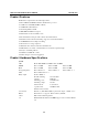
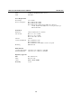
W311/321/341 Hardware User’s Manual Introduction WLAN Communication Standard Compliance 802.11a/b/g Radio Frequency Type DSSS, CCK, OFDM Media Access Protocol Carrier Sense Multiple Access with Collision Avoidance (CSMA/CA) Modulation Transmission Distance Security 802.11a/g: OFDM (64-QAM, 16-QAM, QPSK, BPSK) 802.11b: DSSS (DBPSK, DQPSK, CCK) 5.15 to 5.35 GHz: 15 dBm @6 Mbps; 12 dBm @54 Mbps 5.725 to 5.825 GHz: 15 dBm @6 Mbps; 12 dBm @54 Mbps USA: 2.412 to 2.462 GHz (IEEE802.
W311/321/341 Hardware User’s Manual LAN Serial Power Requirements Power Input Power Consumption Mechanical Dimension (W × D × H) Introduction 10 M/Link, 100 M/Link (RJ45 connector) TxD, RxD 12 to 48 VDC W311: 400 mA @ 12 VDC W321: 400 mA @ 12 VDC W341: 600 mA @ 12 VDC with no USB devices attached 1.
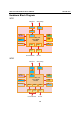
W311/321/341 Hardware User’s Manual Introduction Hardware Block Diagram W311 Ethernet 802.11a/b/g LAN WLAN PHY Power Circuit MAC 16MB RAM MOXA ART CPU 32-bit ARM9 192 MHz 8MB Flash RTC Watchdog UART UART Serial Port 1 Console Port RS-232/422/485 SD Function RS-232 W321 Ethernet LAN 802.
W311/321/341 Hardware User’s Manual Introduction W341 802.11a/b/g Ethernet USB 2.
2 Chapt er 2 H a rdw a re I nt roduc t ion The W300 series hardware is compact, well-designed, and built rugged for industrial applications. LED indicators help you monitor the performance and identify trouble spots. Multiple ports allow the connection of different devices for wireless operation. With the reliable and stable hardware platform that is provided, you may devote your attention to the development of your application.
W311/321/341 Hardware User’s Manual Hardware Introduction Appearance W311 Wireless LAN Antenna Ethernet (10/100BaseTx) 12 to 48 VDC Serial Console Port Internal SD Slot for Storage Expansion (remove cover to access) P1 Serial Port (RS-232/422/485) W321 Wireless LAN Antenna Ethernet (10/100BaseTx) 12 to 48 VDC Serial Console Port Internal SD Slot for Storage Expansion (remove cover to access) Serial Port 1 (RS-232/422/485) Serial Port 2 (RS-232/422/485) 2-2
W311/321/341 Hardware User’s Manual Hardware Introduction W341 Top View Relay Output USB 2.0 Host Internal SD Slot for Storage Expansion (remove cover to access) LAN USB Reset Button RELAY Reset NO COM NC 12-48V Ethernet 10/100BaseTX 12 to 48 VDC Wireless LAN antenna Front View USB 2.
W311/321/341 Hardware User’s Manual Hardware Introduction Dimensions 26 mm (1.02 in) 77 mm (3.03 in) 88 mm (3.46 in) 100 mm (3.94 in) 2-4 148.1 mm (5.83 in) 43 mm (1.69 in) 25 mm (0.98 in) 111 mm (4.
W311/321/341 Hardware User’s Manual Hardware Introduction 26 mm (1.02 in) 77 mm (3.03 in) 88 mm (3.46 in) 100 mm (3.94 in) 2-5 148.1 mm (5.83 in) 43 mm (1.69 in) 25 mm (0.98 in) 111 mm (4.
W311/321/341 Hardware User’s Manual Hardware Introduction W341 USB LAN RELAY Reset NO COM NC 40.5 mm (1.59 in) 150 mm (5.91 in) 161 mm (6.34 in) 173 mm (6.81 in) 2-6 137.1 mm (5.40 in) 35 mm (1.38 in) 25 mm (0.98 in) 100 mm (3.93 in) 12-48V 38 mm (1.
W311/321/341 Hardware User’s Manual Hardware Introduction LED Indicators Please note that the W311 does not include an SD slot, so it will not have an SD LED.
W311/321/341 Hardware User’s Manual Hardware Introduction Real Time Clock The embedded computer’s real-time clock is powered by a lithium battery. We strongly recommend that you NOT replace the lithium battery on your own. If the battery needs to be changed, please contact the Moxa RMA service team. AT T EN T I ON There is a risk of explosion if the wrong type of battery is used. To avoid this potential danger, always be sure to use the correct type of battery.
3 Chapt er 3 H a rdw a re Conne c t ion De sc ript ion W300 Series wireless embedded computers are equipped for multiple types of connections. WLAN, Ethernet, and multiple serial interfaces are built into every model, including a serial console port for monitoring of bootup messages. Select models also include an SD slot for storage expansion, USB ports for additional device and storage options, and relay output connections.
W311/321/341 Hardware User’s Manual Hardware Connection Description Wiring Requirements This section describes how to connect serial devices to the embedded computer. You should heed the following common safety precautions before proceeding with the installation of any electronic device: y Use separate paths to route wiring for power and devices. If power wiring and device wiring paths must cross, make sure the wires are perpendicular at the intersection point.
W311/321/341 Hardware User’s Manual Hardware Connection Description AT T EN T I ON This product should be mounted to a well-grounded mounting surface such as a metal panel. SG V- V+ SG: The Shielded Ground (sometimes called Protected Ground) contact is the left most contact of the 3-pin power terminal block connector, as viewed from the angle shown here. Connect the SG wire to an appropriate grounded metal surface.
W311/321/341 Hardware User’s Manual Hardware Connection Description Connecting to a Serial Device Your serial device can plug into the embedded computer’s serial port using a serial cable. Serial ports P1 to P4 have male DB9 connectors and can be configured for RS-232, RS-422, or RS-485 communication through software.
W311/321/341 Hardware User’s Manual Hardware Connection Description The SD card will be mounted at /mnt/sd. Detailed installation instructions are shown below: Step 1: Use a screwdriver to remove the screws holding the SD slot’s outer cover. Step 2: After removing the cover, insert the SD memory card as shown.
W311/321/341 Hardware User’s Manual Hardware Connection Description W341 The SD slot is located on the front panel of the W341. To install an SD card, you must first remove the SD slot’s protective cover to access the slot, and then plug the SD card directly into the slot. The SD card will be mounted at /mnt/sd. Detailed installation instructions are shown below: Step 1: Use a screwdriver to remove the screws holding the SD slot’s outer cover, and then remove the cover.
W311/321/341 Hardware User’s Manual Hardware Connection Description USB (W341 only) The W341 includes two USB 2.0 hosts. These hosts can be used for an external flash disk or hard drive in order to store large amounts of data. USB 2.0 Ports RELAY 3-7 NC COM The W341 includes a relay output channel. There is a 3-pin terminal block for the relay output connection, with pinouts as shown in the figure.
A Appendix A Re gula t ory Approva l St a t e m e nt This device complies with part 15 of the FCC Rules. Operation is subject to the following two conditions: (1) This device may not cause harmful interference, and (2) this device must accept any interference received, including interference that may cause undesired operation. This equipment complies with FCC radiation exposure limits set forth for an uncontrolled environment.