
User's Manual
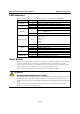


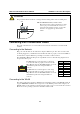
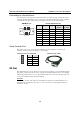

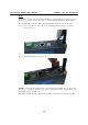
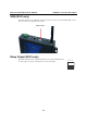
Table Of Contents

W311/321/341 Hardware User’s Manual Hardware Connection Description
ATT ENT ION
This product should be mounted to a well-grounded mounting surface such as a metal panel.
V+V-
12-48V
SG
SG: The Shielded Ground (sometimes called
Protected Ground) contact is the left most contact
of the 3-pin power terminal block connector, as
viewed from the angle shown here. Connect the
SG wire to an appropriate grounded metal
surface.
Connecting Data Transmission Cables
This section describes how to connect cables for the network, serial devices, and serial COM
terminal.
Connecting to the Network
Plug your network cable into the embedded computer’s Ethernet port. The other end of the cable
should be plugged into your Ethernet network. When the cable is properly connected, the LEDs on
the embedded computer’s Ethernet port will glow to indicate a valid connection.
The 10/100 Mbps Ethernet LAN port uses 8-pin RJ45 connectors. The following diagram shows
the pinouts for these ports.
The LED indicator on the right glows a solid green
color when the cable is properly connected to a 100
Mbps Ethernet network. The LED will flash on and off
when Ethernet packets are being transmitted or
received.
8 1
The LED indicator on the left glows a solid orange
color when the cable is properly connected to a 10
Mbps Ethernet network. The LED will flash on and off
when Ethernet packets are being transmitted or
received.
Pin Signal
1 ETx+
2 ETx-
3 ERx+
4 ---
5 ---
6 ERx-
7 ---
8 ---
Connecting to the WLAN
The wireless embedded computer is WLAN ready and includes an 802.11 a/b/g WLAN module. It
supports WEP, WPA and WPA2 data encryption. To verify WLAN operation, first configure your
WLAN settings on the embedded computer using the serial console or a wired network connection.
Please refer to the operating system user’s manual for further detail.
3-3