Moxa IEEE 802.11a/b/g/n Wireless Module WAPN005 User’s Manual First Edition, April 2014 www.moxa.com/product © 2014 Moxa Inc. All rights reserved.
Moxa IEEE 802.11a/b/g/n Wireless Module WAPN005 User’s Manual The software described in this manual is furnished under a license agreement and may be used only in accordance with the terms of that agreement. Copyright Notice © 2014 Moxa Inc. All rights reserved. Trademarks The MOXA logo is a registered trademark of Moxa Inc. All other trademarks or registered marks in this manual belong to their respective manufacturers.
Table of Contents 1. Introduction...................................................................................................................................... Overview ........................................................................................................................................... Features ............................................................................................................................................ Specifications .............................
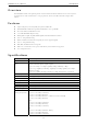
1 1. Introduction This chapter briefly introduces the overview, features and the specifications of the WAPN005 wireless module.
WAPN005 User's Manual Introduction Overview Moxa WAPN005 module is designed to provide wireless communication for all wireless device based systems. It communicates via the standard 802.11a/b/g/n protocols, and uses the AR9344 wireless chipset from Atheros. Features Dynamic frequency selection (DFS) in required 5-GHz bands All-CMOS MIMO solution interoperable with IEEE 802.11a/b/g/n WLANs No external VCOs or SAW filters needed 2.
WAPN005 User's Manual Introduction 1-3
2 2. Getting Started This chapter describes the hardware introduction, installation, and software installation.
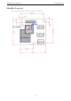
WAPN005 User's Manual Getting Started Module Layout Refer to the following figure for the module layout of the WAPN005.
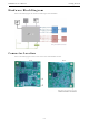
WAPN005 User's Manual Getting Started Hardware Block Diagram Refer to the following figure the hardware block diagram of the WAPN005. Connector Location Refer to the following figures for the connector location of the WAPN005 module.
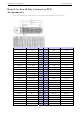
WAPN005 User's Manual Getting Started Board-to-board Bus Connector PIN Assignments Refer to the following figures and table for the PIN assignment of the WAPN005 module connector. Function Connect to Pin Pin Function Connect to 3.3v 3.3v 1 2 GND GND 3.3v 3.3v 3 4 GND GND 3.3v 3.3v 5 6 ERXD3 PHY RGMII 3.3v 3.3v 7 8 ERXD2 PHY RGMII 3.3v 3.3v 9 10 ERXD1 PHY RGMII 3.3v 3.3v 11 12 ERXD0 PHY RGMII 3.3v 3.
WAPN005 User's Manual Getting Started GPIO 2 UR_DTR 53 54 EMDC GIGA PHY GND GND 55 56 EMDIO GIGA PHY GPIO 11 Reset 57 58 GND GND GND GND 59 60 GND GND GPIO 12 LAN 10/100 61 62 TXP0 10/100 LAN GND GND 63 64 TXN0 10/100 LAN GPIO 15 Reserved 65 66 GND GND GND GND 67 68 RXP0 10/100 LAN SYS_RST_L GIGA PHY Reset 69 70 RXN0 10/100 LAN AVDD18 Fast Ethernet bios 71 72 GND GND AVDD18 Fast Ethernet bios 73 74 GND GND AVDD18 Fast Ethernet bios 75 76
A A . Regulatory Statement Approval Federal Communication Commission Interference Statement This equipment has been tested and found to comply with the limits for a Class B digital device, pursuant to Part 15 of the FCC Rules. These limits are designed to provide reasonable protection against harmful interference in a residential installation.
WAPN005 User's Manual Regulatory Statement Approval RF Exposure Warning This equipment must be installed and operated in accordance with provided instructions and the antenna(s) used for this transmitter must be installed to provide a separation distance of at least 20 cm from all persons and must not be co-located or operating in conjunction with any other antenna or transmitter.