
User's Manual
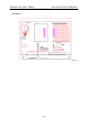
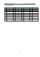

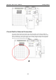
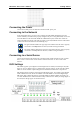

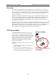
Table Of Contents

WE-2100T Series User’s Manual Getting Started
3-4
Connecting the Power
Connect the 12 VDC power line with the evaluation boards’ power jack.
Connecting to the Network
In the development stage, you may want to configure the WE-2100T with Ethernet since the
wireless LAN may not work before properly configured. If you are using WE-2100T, connect one
end of the Ethernet cable to the WE-2100T-ST’s RJ45 Ethernet port, and the other end of the
cable to the Ethernet network. If the cable is properly connected, the RJ45 connector will indicate
a valid connection to the Ethernet in the following ways:
LAN
The green indicator LED in the upper right corner blinks when the cable is properly
connected to a 100 Mbps Ethernet network, and data is being transmitted.
LAN
The yellow indicator LED in the upper left corner blinks when the cable is properly
connected to a 10 Mbps Ethernet network, and data is being transmitted.
Connecting to a Serial Device
Connect the serial data cable between the evaluation boards and the serial device. The “Console
Port” or “P1” is used as serial console interface and the “Data Port” or “P2” is used as data
interface.
DI/O Settings
WE-2100T supports up to 9 digital I/Os. All 9 digital I/Os are GPIO (General Purpose I/O) that
allow you to set to “digital output” or “digital input” mode by software. On the evaluation board,
LEDs are used to simulate output loading whereas the DIP switch simulates an input device.
DIO mode for physical wiring is selected by the DIO mode jumper. For example, when the DIO
mode of DIO1 is set to DI, the circuit of DIO1 on the WE-2100T is connected to Digital Input
DIP switch, digit 1. When the firmware of the WE-2100T sets DIO1 to digital input mode, you
can check the DIO1 status with the Windows utility or Web browser. When you change digit 1 of
the switch, the changes appear on the Web browser.