
User's Manual
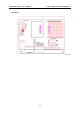
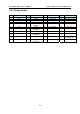

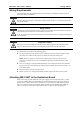
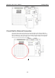
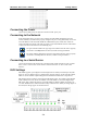

Table Of Contents

WE-2100T Series User’s Manual Getting Started
3-5
1. First, use the DIO selectable jumpers to set the D/O modes, as shown below.
2. After the DIO modes are set, use the Digital Input DIP Switches to configure the status for
DI0 – DI3. You can either configure the status to “Low” or “High.” If you wish to configure
DI0’s status to “Low” and the others to “High,” set DIP Switch 1 to the “ON” position and
the others to the “OFF” position, as shown below.
3. DO4 – DO8’s status must be configured with the Web Console. If you configure DO4’status
to “Low” and the others to “High,” the DO4’s LED will show solid green, and the other
LEDs will not light up. Refer to chapter 6 for more configuration details.
Digital Output LED Circuit Design
The figure shown below is the digital output LED circuit design. The design is called “Sink.”
3.3V
Dout
For developing your own applications, you need to be aware of the voltage limits shown below.
The output electric circuit is 1 mA
Min. Max. Unit Conditions
Low-level
Input Voltage
Maximum voltage when DI is set
to “Low” status.
----- 0.3xVCC V
High-level
Input Voltage
Minimum voltage when DI is set
to “High” status.
0.7xVCC ----- V
Low-level
Input Voltage
Maximum voltage when DO is set
to “Low” status.
----- 0.4 V
High-level
Input Voltage
Minimum voltage when DO is set
to “High” status
2.4 ----- V
Digital Output’s output current carries only 1 mA.