Moxa 900MHz PCI Module WFS001 User’s Manual www.moxa.com First Edition, July 2014 2014 Moxa Inc. All rights reserved. Reproduction without permission is prohibited.
WFS001 User’s Manual The hardware and software described in this manual is furnished under a license agreement and may be used only in accordance with the terms of that agreement. Copyright Notice Copyright 2014 Moxa Inc. All rights reserved. Reproduction without permission is prohibited. Trademarks MOXA is a registered trademark of Moxa Inc. All other trademarks or registered marks in this manual belong to their respective manufacturers.
Moxa Europe: Tel: +49‐89‐3 70 03 99‐0 Fax: +49‐89‐3 70 03 99‐99
Table of Contents Chapter 1 Introduction Overview Features Specification Chapter 2 Getting Started Module Layout Block Diagram Hardware Installation Software Installation
WFS001 User’s Manual Introduction 1 Chapter 1 The following topics are covered in this chapter: OverviewFeatures Specifications Introduction
WFS001 User’s Manual Introduction Overview WFS001 PCI Module is designed to provide wireless communication for all wireless device based systems. It communicates via the standard 802.11b/g protocols but with transmission frequency shifted to 900MHz (902‐928MHz). The WFS001 uses the AR5414 wireless chipset from Atheros. This module is connected to the PCI bus through a PCI connector and special circuitry to allow for compatibility with either 3.3V or 5V PCI signaling..
2 Chapter 2 Getting Started This chapter covers the module layout, and block diagram, hardware installation of the WFS001. Software installation is covered in the next chapter.
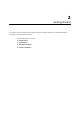
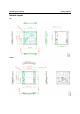
WFS001 User’s Manual Module Layout Top Bottom Getting Started
WFS001 User’s Manual Block Diagram Below is a block diagram of the WFS001.
WFS001 User’s Manual Getting Started Connector Locations Board to Board Connector RF Main Connector RF AUX Connector
WFS001 User’s Manual Getting Started PCI Bus Connector PIN Assignments 3.3V_CON J1 3.3V 3.
WFS001 User’s Manual Getting Started Hardware Installation The WFS001 can be installed into all Moxa wireless system board series. Step for Installation 1. Attach the WLAN antenna to connector J1. 2. If using 2nd WLAN antenna, attach it to connector J2. 3. Install the WFS001 PCI card on the system board. Apply pressure to both bus connectors and gently press the board onto the stack. The board should slide into the matching bus connectors.
WFS001 User’s Manual Getting Started Federal Communication Commission Interference Statement This equipment has been tested and found to comply with the limits for a Class B digital device, pursuant to Part 15 of the FCC Rules. These limits are designed to provide reasonable protection against harmful interference in a residential installation.
WFS001 User’s Manual Getting Started End Product Labeling This transmitter module is authorized only for use in device where the antenna may be installed such that 20cm may be maintained between the antenna and users.