Moxa Industrial Sub-1G Module ZB-DCU3-T, ZB-PM3-T, ZB-WAN1-T User’s Manual First Edition, August 2014 www.moxa.com/product © 2014 Moxa Inc. All rights reserved. Reproduction without permission is prohibited.
Moxa Industrial Sub-1G Module ZB-DCU3-T, ZB-PM3-T, ZB-WAN1-T User’s Manual The software described in this manual is furnished under a license agreement and may be used only in accordance with the terms of that agreement. Copyright Notice © 2014 Moxa Inc. All rights reserved. Trademarks The MOXA logo is a registered trademark of Moxa Inc. All other trademarks or registered marks in this manual belong to their respective manufacturers.
Table of Contents 1. Introduction ........................................................................................................ 1-1 Overview .................................................................................... 1-2 Features ..................................................................................... 1-2 Specifications ............................................................................ 1-2 2. Getting Started .........................................................
1 1.
Overview Moxa Sub-1G module(ZB-DCU3-T, ZB-PM3-T, ZB-WAN1-T) uses ATMEL wireless microcontroller which provides a comprehensive solution with large memory(256KB Flash and 16KB SRAM), high CPU and radio performance and all RF components included. The module is a range of ultra low power, high performance surface mount modules targeted at Sub-1G networking applications, enabling users to realize products with minimum time to market and at the lowest cost.
Environmental Limits Operating Temperature: -40 to 75°C (-40 to 167°F) Operating Humidity: 5 to 95% RH Storage Temperature: -40 to 85°C (-40 to 185°F) Physical Characteristics Dimension: ZB-DCU3-T/ZB-WAN1-T (48x30x1.6mm), ZB-PM3-T (45x38x1.6mm) Standard and Certifications EMC: CE (EN55022 and EN55024 Class A), FCC Part 15 Subpart B Class A Reliability Automatic Reboot Trigger: Built-in WDT (watchdog timer) MTBF (meantime between failures): Over 10 years Warranty Warranty Period: 5 years Details: See www.
2 2. Getting Started This chapter covers the module layout, and block diagram, hardware installation of the Sub-1G module. Software installation is covered in the next chapter.
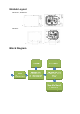
Module Layout ZB-DCU3-T, ZB-WAN1-T + = ZB-PM3-T + Block Diagram =
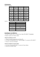
PIN Define ZB-DCU3-T, ZB-WAN1-T PIN Number PIN Function PIN Number PIN Function 1 3.3V 2 3.3V 3 GND 4 GND 5 GND 6 GND 7 NC 8 NC 9 NC 10 NC 11 RXD 12 NC 13 TXD 14 NC 15 NC 16 NC 17 NC 18 NC 19 NC 20 RESET ZB-PM3-T PIN Number 1 2 3 4 PIN Function VCC TXD RXD 5 NC 6 GND 7 GND RST Hardware Installation The Sub-1G Module can be installed into Moxa DCU-8620-T Embedded Computer system and Power Meter. Steps for Installation on DCU 1.
Software Installation After physically installing the Sub-1G module, the module will be recognized on the new system board after the following steps. Steps for Installation 1. Apply power to the system board. 2. Run DCU-8620-T application program. Make sure it could communicate with Sub-1G module(ZB-WAN1-T and ZB-DCU3-T). 3. Apply power to the Power Meter. Make sure the LED of “Ready” light-on on Power Meter. 4.
A A. Regulatory Statements Federal Communication Commission Interference Statement This device complies with Part 15 of the FCC Rules. Operation is subject to the following two conditions: (1) This device may not cause harmful interference, and (2) this device must accept any interference received, including interference that may cause undesired operation. This equipment has been tested and found to comply with the limits for a Class B digital device, pursuant to Part 15 of the FCC Rules.
Radiation Exposure Statement: This equipment complies with FCC radiation exposure limits set forth for an uncontrolled environment. This equipment should be installed and operated with minimum distance 20cm between the radiator & your body. This device is intended only for OEM integrators under the following conditions: 1) The antenna must be installed such that 20 cm is maintained between the antenna and users, and 2) The transmitter module may not be co-located with any other transmitter or antenna.