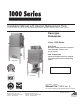
Installation Manual with Service Replacement Parts For Champion Models: DH-1000, DL-1000 • Moyer Diebel Models: MD1000HT, MD1000LT • Valu-Clean Models: VC1000, VC1000HT Door-type Dishwasher Model: 1000 Series High Temp Hot water sanitizing machine w/ pumped rinse and built-in stainless steel electric booster Low Temperature Chemical sanitizing machine w/ pumped rinse and 3 built-in chemical dispensing pumps High Temp C US Dishwasher serial no. Low Temp Issue Date: 4.23.08 Manual P/N 114313 rev.
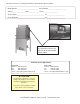
For future reference, record your dishwasher information in the box below. Model Number__________________________ Serial Number_______________________ Voltage________________Hertz_____________ Phase__________________ Service Agent __________________________________ Tel:______________________ Parts Distributor _________________________________ Tel:______________________ For all models: The data plate mounts to the right-side of the top-mounted control cabinet.
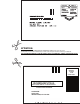
ATTENTION: Complete the back of the POSTAGE PAID WARRANTY CARD below, then cut along the dashed lines and mail immediately to make sure that your machine warranty is validated. USE CANADIAN WARRANTY CARD IN CANADA AND USA WARRANTY CARD IN THE UNITED STATES. NO POSTAGE NECESSARY IF MAILED IN THE UNITED STATES BUSINESS REPLY MAIL FIRST-CLASS MAIL PERMIT NO.
8"33"/5: 3&(*453"5*0/ $"3% .
1000 Series - Revision History Revision History • The Revision History can contain part number changes, new instructions, or information that was not available at print time. • We reserve the right to make changes to these instructions without notice and without incurring any liability by making the changes.. • Equipment owners may request revised instructions, at no charge, by calling 1 (800) 858-4477 in the USA or by caling 1 (800) 263-5798) in Canada.
Dear Owner: Thank you for choosing our dishwasher. We appreciate your business. This manual covers: High Temp High temperature door-type dishwasher with standard built-in booster in 40°F/22°C rise or an optional 70°F/39° C rise booster. Low Temp Low temperature chemical sanitizing door-type dishwasher with built-in chemical dispensing pumps for detergent, rinse-aid, and sanitizer.
1000 Series - Table of Contents Revision History... . ............................................................................................................ i Limited Warranty. .............................................................................................................. iv High Temperature Door-Type Dishwasher Installation Guide............................................................................................................. 1 Unpack and Place.............
1000 Series - Limited Warranty Limited Warranty Valu-Clean, Champion or Moyer Diebel (hereinafter referred to as the Company), P.O. Box 4982, Winston-Salem, North Carolina 27115 & 2674 N. Service Road, Jordan Station, Canada, L0R 1S0, warrants machines, & parts, as set out below.
1000 Series HT - Installation Guide Installation Guide Unpack and Place (1000 Series HT) 1. Check the corrugated box that protected the dishwasher during shipment for punched holes or impact marks. 2. Inspect the shipping pallet for splintered or broken boards. 3. Inspect the exterior of the dishwasher while still mounted on the pallet for signs of damage. 4. Contact the freight company immediately if damage is found and save all packing for inspection to verify your damage claim. 5.
00 Series HT - Installation Guide Installation Guide Unpack and Place (1000 Series HT) 1. The installation of your dishwasher must be performed by qualified service personnel. 2. Problems due to improper installation are not covered by the Warranty. 3. The dishwasher data plate is located on the right-side of the top-mounted control cabinet cover. 4. Study the configuration diagrams below. They show the 2 ways that the dishwasher may be positioned.
1000 Series HT - Installation Guide Installation Guide Unpack and Place (1000 Series HT) 1. All dishwashers ship in the straight-through configuation. 2. Relocate the tracks and remove the wall-side door link components to convert the dishwasher for corner operation.
1000 Series HT - Installation Guide Installation Guide Unpack and Place (1000 Series HT) 1. Compare the dishwasher and site utility connections. 2. Level the dishwasher by adjusting the bullet feet. 3. Raise the doors and check the door clearance to the ceiling. 4. Move the dishwasher to its permanent location. Note: Installers must follow applicable sanitation, safety, plumbing, and electrical codes and regulations; and work in accordance with best practices for dishwasher installation.
1000 Series HT - Installation Guide Installation Guide Electrical Connection (1000 Series HT) Warning: The dishwasher must be electrically grounded according to all local codes and regulations governing the installation of electrical service. Warning: Disconnect the main electric supply and place a tag at the fuse or disconnect switch indicating that work is being performed on that circuit. 1. Locate the screw on each side of the top-mounted control cabinet. 2.
1000 Series HT - Installation Guide Installation Guide Water Connection (1000 Series HT) 1. Locate the built-in stainless steel booster on the left-side of the dishwasher. Note: The existing hot water supply lines to the dishwasher must be 3/4" NPT or larger. To the best of your ability inspect, and verify that all supply piping meets the 3/4" NPT requirement.
Blank page This page intentionally left blank 7
1000 Series HT - Installation Guide Installation Guide Drain Connection (1000 Series HT) Continued from page 6 1. Locate the dishwasher drain connection underneath the machine frame. 2. Install a drain line conforming to local plumbing and health regulations. Drain: 1-7/8" stainless steel, slip-fit hose connection Max flow: 15 US gal/min. (13.5 Imperial gal/min) 57liters/min. Ventilation (1000 Series HT) 1.
1000 Series HT - Installation Guide Installation Guide Chemical Dispensers (1000 Series HT) 1. The 1000 Series HT high temperature dishwasher sanitizes with 180-195° F/82-91° C hot final rinse water. 2. Do not connect a sanitizer chemical dispenser to the 1000 Series HT. 3. You may wish to contact a chemical supplier to supply the chemical dispensers and chemicals for liquid detergent and liquid rinse-aid. (Consult your local listings). 4.
1000 Series HT - Installation Guide Installation Guide Chemical Dispensers (1000 Series HT) Continued from page 9 115VAC Power Connections for Chemical Dispensers FOR QUALIFIED INSTALLERS ONLY Warning: Chemical dispensers must be electrically grounded in compliance with applicable electric codes. Warning: Disconnect the main electric supply and place a tag at the fuse or disconnect switch indicating that work is being performed on that circuit.
1000 Series HT - Installation Guide L1 1 L2 2 L2 Installation Guide Chemical Dispensers (1000 Series HT) GND 3 208VAC/3PH/60/3 Main terminal block and ground lug Detergent dispensing pump & cycle Timer cam No.5 with timer microswitch 5. The main terminal board is the termination point for the incoming power and earth ground which is also called the chassis ground. 6. Chemical dispensers (not supplied by Factory) must be grounded to chassis to protect the dishwasher circuits if possible.
1000 Series HT - Installation Guide Installation Guide Chemical Dispensers (1000 Series HT) Continued from page 11 10. There are 8 Cams on the cycle timer. They are numbered 1-8 starting at the timer motor side of the assembly. 11. Look at the underside of the detergent and the Rinse-aid timer microswitches and identify the common terminals. 12. Connect the hot lead for the detergent pump to the common terminal of Cam Switch No. 5. Make the connection using a 12-14 slip-on terminal.
1000 Series HT - Installation Guide Installation Guide Chemical Dispensers (1000 Series HT) Caution: The NEUTRAL RETURN (#2 white wires) and Chassis Ground are not the same point electrically. Improper wiring to these points may result in unusual voltage readings and damage to the dishwasher's electrical circuits. STOP WORKING ON THE DISHWASHER AT ONCE, if you do not know the difference between a neutral return and chassis ground.
1000 Series HT - Installation Guide Installation Guide Chemical Dispensers (1000 Series HT) Priming the chemical dispensers (Factory dispensers only) 1. Factory dispensers are optional equipment;however, an automatic dispenser mustbe installed by someone in lieu of the factory. 2. The dispensers are mounted on the right-hand side of the lower wash tank. 3. Chemical pick-up tubes are inserted into their respective containers. 4.
1000 Series HT - Installation Guide Installation Guide Initial Start-up (1000 Series HT) CAUTION DO NOT flip the dishwasher power switch "ON" until you read the instructions below. 1. The built-in stainless steel electric booster was shipped without water. 2. A manila card located above the power switch explains how to turn the machine on for the first time. See step No. 10 on the next page for the first DISHWASHER POWER UP procedure. Let's begin the Initial Start-up: 1.
1000 Series HT - Installation Guide Installation Guide Initial Start-up (1000 Series HT) Continued from page 15 5. Check that the following utilities are connected to the dishwasher and ready for use: Electrical service Hot water supply Drain Ventilation (if required by local regulations). 6. Check the chemical connections and chemical containers to ensure that enough chemical supplies are available. 7. Turn on the water supply to the dishwasher. 8.
1000 Series HT - Installation Guide Installation Guide Initial Start-up (1000 Series HT) POWER UP THE DISHWASHER: As stated on page 15, the dishwasher power switch must not be turned without reading the instructions below.: WASH 170 70 80 100 105 C F 0 NSF MODEL W 22 100 80 60 95 0 210 20 20 RINSE PRESSURE 180 90 50 40 P/N 108391 200 120 60 FILL 60 40 190 160 0 14 psi CYCLE POWER ON 80 20 CHAMPION INDUSTRIES, INC. WINSTON-SALEM, NC 0 100 DRAIN USG OFF 13.
1000 Series HT - Installation Guide Installation Guide Initial Start-up (1000 Series HT) 18. Operate the dishwasher for 10 cycles. Monitor the wash and final rinse gauges located on the lower front panel of the dishwasher to ensure the machine is maintaining the proper temperatures. In the USA, the NSF standards are: 150° F/66° C minimum wash temperature 180° F/82° C minimum final rinse temperature Note: In Canada, sanitary standards are regulated by each province.
Operation - 1000 Series HT Operation (1000 Series HT) 1. Make sure there is adequate supply of liquid detergent and rinse-aid. Check the chemical containers and refill if necessary. 2. Ensure internal circular tank screen, upper and lower spray arms and lower external scrap screen are clean and in place. 3. Close door. Turn POWER switch to the “ ON ” position.
1000 Series HT - Operation Operation (1000 Series HT) The Rinse Sentry Feature The 1000 Series HT Rinse Sentry automatically monitors the final rinse water temperature in the built-in stainless steel electric booster heater. If the final rinse water in the booster falls below 180°F/82°C, the Rinse Sentry will extend the dishwasher's wash cyle time in order to give the booster heater additional time to provide the 180°F/82°C water temperature required. Sanitization using hot final rinse water: 1.
Cleaning and Maintenance - 1000 Series HT Cleaning and Maintenance Cleaning and Maintenance (1000HT Series) 1. Leave the machine power switch in the ON position. Doors are fully closed. 2. Push and hold the “FILL/DRAIN” switch down in the “DRAIN” position for approximately 15-20 seconds. The water in the wash tank will drain completely. 3. Raise doors fully. Use caution, as metal surfaces may be hot. Allow interior to cool. 4. Rinse the interior of the dishwasher with fresh water.
1000 Series HT - Cleaning and Maintenance Cleaning and Maintenance Cleaning and Maintenance (1000 Series HT) Thoroughly cleaning your dishwasher every day is very best maintenance that you can do!! Daily Maintenance 1. Keep your dishwasher and the surrounding area spotlessly clean. 2. Immediately report loose, broken or missing parts to your supervisor. 3. Check drains for flow restrictions. 4. Check the dishwasher for leaks. 5. Operate the dishwasher as explained in this manual.
1000 Series HT - Troubleshooting Troubleshooting - (1000 Series HT) In order to find the cause of a breakdown or abnormal operating condition in your dishwasher please ensure that: 1. All switches are ON 2. Drain overflow tube is in place and seated 3. Wash pipe and rinse nozzles are clean 4. Spray arms are in their proper positions 5. Round screen is properly positioned 6. Detergent, sanitizer and rinse additive dispensers are adequately filled 8. Doors are fully closed.
1000 Series HT - Troubleshooting Troubleshooting (continued) (1000 Series HT) Condition Cause Solution Insufficient rinse or no rinse Faulty pressure regulating valve... Clean or replace Improper setting on pressure regulating valve............................. Set static pressure to 35 psi Clogged rinse nozzle and/or pipe................................................ Clean with paper clip/delime Improper water line size................
1000 Series - Installation Guide Model 1000 Series LT Installation Guide 25
1000 Series LT - Installation Guide Installation Guide Unpack and Place (1000 Series LT) 1. The installation of your dishwasher must be performed by qualified service personnel. 2. Problems due to improper installation are not covered by the Warranty. 3. The dishwasher data plate is located on the right-side of the top-mounted control cabinet cover. 4. Study the configuration diagrams below. They show the 2 ways that the dishwasher may be positioned.
1000 Series LT - Installation Guide Installation Guide Unpack and Place (1000 Series LT) 1. All dishwashers ship in the straight-through configuation. 2. Relocate the tracks and remove the wall-side door link components to convert the dishwasher for corner operation.
1000 Series LT - Installation Guide Installation Guide Unpack and Place (1000 Series LT) 1. Compare the dishwasher and site utility connections. 2. Level the dishwasher by adjusting the bullet feet. 3. Raise the doors and check the door clearance to the ceiling. 4. Move the dishwasher to its permanent location. Note: Installers must follow applicable sanitation, safety, plumbing, and electrical codes and regulations; and work in accordance with best practices for dishwasher installation.
1000 Series LT - Installation Guide Installation Guide Electrical Connections (1000 Series LT) Warning: The dishwasher must be electrically grounded according to all local codes and regulations governing the installation of electrical service. Warning: Disconnect the main electric supply and place a tag at the fuse or disconnect switch indicating that work is being performed on that circuit. 1. Locate the control cabinet keys on the rear of the control cabinet. 2.
1000 Series LT - Installation Guide Installation Guide Water Connection (1000 Series LT) Water supply: 3/4" NPT hot water supply (140°F/60°C minimum) 20 ± 5 psi/138 ± 35kPa flow pressure. Installation of 0-60 psi/0-414 kPa pressure gauge is recommended. Note: Plumbing installer must connect a 3/4" NPT hot water supply line to the dishwasher. A 3/4" pressure regulating valve (PRV) (not supplied) must be installed in the water supply line and adjusted to 20 ± 5 psi/138 ± 35 kPa flow pressure.
1000 Series LT - Installation Guide Installation Guide Drain Connection (1000 Series LT) 1. Locate the dishwasher drain connection underneath the machine frame. 2. Install a drain line conforming to local plumbing and health regulations. Drain: 1-7/8" stainless steel, slip-fit hose connection Max flow: 15 Us gal/min. (13.5 Imperial gal/min) 57liters/min. Ventilation 1000 Series LT 1.
1000 Series LT - Installation Guide Installation Guide Chemical Dispensers (1000 Series LT) Note: Manual dosing of detergent or rinse-aid is NOT RECOMMENDED for the 1000 Series LT dishwasher. Poor washing results may result if manual dosing is employed.. Note: Cartridge detergent systems are NOT RECOMMENDED for the 1000 Series LT dishwasher. Poor washing results may result if installed on this model. Note: The 1000 Series LT chemical dispensers are standard equipment.
1000 Series LT - Installation Guide 1. Installation Guide Initial Start-Up (1000 Series LT) Check that the following utilities are connected to the dishwasher and ready for use: Electrical service Hot water supply Drain Ventilation (if required by local regulations). 2. Check the chemical connections and chemical containers to ensure that enough chemical supplies are available. 3. Turn on the water supply to the dishwasher. 4.
Blank Page This Page Intentionally Left Blank 34
1000 Series LT - Installation Guide Installation Guide Initial Start-Up (1000 Series LT) POWER UP THE DISHWASHER: 1. Flip the dishwasher power switch UP to turn on. 2. Turn on the main power switch at the service disconnect switch. 3. Release the fill switch. 4. Open the dishwasher door fully and check the water level inside the tank. The proper water level is just below the overflow tube and 3" [76 mm] from the lower manifold measuring up the tank toward the rear of the dishwasher. 5.
1000 Series LT - Operation Operation How to Operate your Dishwasher (1000 Series LT) 1. Make sure there is adequate supply of liquid detergent and rinse-aid, and sanitizer. Check the chemical containers and refill if necessary. 2. Ensure the overflow tube/drain ball are clean and in place, and the circular pump screen, upper and lower spray arms and lower external scrap screen are clean and in place. 3. Close door. Turn POWER switch to the “ON ” position.
1000 Series LT - Cleaning and Maintenance Cleaning and Maintenance How to Clean your Dishwasher (1000 Series LT) 1. Leave the machine power switch in the ON position. Doors are fully closed. 2. Push and hold the “FILL/DRAIN” switch down in the “DRAIN” position for approximately 15-20 seconds. The water in the wash tank will drain completely. 3. Raise doors fully. Use caution, as metal surfaces may be hot. Allow interior to cool. 4. Rinse the interior of the dishwasher with fresh water.
1000 Series LT -Cleaining and Maintenance Cleaning and Maintenance How to Clean your Dishwasher (1000 Series LT) Warning: Electrocution or chemical burns may occur if untrained persons attempt the deliming procedure. Only qualified service personnel should delime the dishwasher. 1. The 1000 Series LT is equipped with a delime switch on the left front side inside the top-mounted control cabinet. 2.
1000 Series LT - Cleaning and Maintenance Cleaning and Maintenance How to Maintain your Dishwasher (1000 Series LT) Thoroughly cleaning your dishwasher every day is very best maintenance that you can do!! Daily Maintenance 1. Keep your dishwasher and the surrounding area spotlessly clean. 2. Immediately report loose, broken or missing parts to your supervisor. 3. Check drains for flow restrictions. 4. Check the dishwasher for leaks. 5. Operate the dishwasher as explained in this manual.
1000 Series LT -Troubleshooting Troubleshooting In order to find the cause of a breakdown or abnormal operating condition in your dishwasher please ensure that: 1. 2. 3. 4. 5. 6. 8. All switches are ON Drain overflow tube is in place and seated Wash pipe and rinse nozzles are clean Spray arms are in their proper positions Round screen is properly positioned Detergent, sanitizer and rinse additive dispensers are adequately filled Doors are fully closed.
1000 Series LT -Troubleshooting Troubleshooting (continued) Condition Cause Solution Low final rinse temperature Low incoming water....................... Check valve to be sure it is clean and ...................................................... operating. Defective thermometer.................. Check for proper setting or replace Machine leaking Leaking at chemical hose.............. Pump seal leaking......................... Leaking at pump hose...................
Blank Page This Page Intentionally Left Blank 42
1000 Series HT and 1000 Series LT - Service Replacement Parts Service Replacement Parts Models: 1000 Series HT • 1000 Series LT Illustrations Page Wash pump/motor assembly________________________________________________ 45 1000 Series HT • Built-in booster assembly_ ___________________________________ 47 1000 Series HT • Control cabinet enclosure____________________________________ 49 1000 Series HT • Conrtol cabinet assembly_ ___________________________________ 51 1000 Series LT • Control cab
Replacement Parts Item No. Part No.
Replacement Parts 1/4-20 locknut 1/4" washer 1/4-20 locknut 1/4" washer 1/4-20 x 3/4" 1/4 x 20 washer 20 21 22 21 21 23 21 45
Replacement Parts Item No. 46 Part No. Description Qty.
Replacement Parts 1 2 3 4 5 11 6-32 x 1/4" screw 6-32 washer 10 6 17 7 10-32 nylon insert nut and washer 8 16 9 13 12 6 14 15 21 20 18 19 47
Replacement Parts Item No. Part No. Description Qty. Unit 1 331082 control cabinet cover 1 ea 2 107351 power switch 1 ea 3 0508551 green cycle light 1 ea 4 0510399 fill and drain switch 1 ea 5 0510399 detergent /rinse-aid prime switch (optional) 1 ea 6 331078 control cabinet wrap 1 ea 7 0510833-1 std. cntrl. panel decal w/o prime switch/ prior to S/N D5937 1 ea 8 0510833-11 opt. cntrl.
Replacement Parts 1 3 2 4 5 6 7 8 Hood 49
Replacement Parts Item No. 50 Part No. Description Qty. Unit 1 0501403 brass screw 1 ea ---- 0501533 brass nut 1 ea ---- 0501472 brass 1/8” flat washer 1 ea ---- 0501493 brass lock washer 1 ea 2 0504951 terminal block 1 ea 3 105514 booster heat contactor 1 ea 4 106402 fuse block 1 ea 5 0503749 terminal board 1 ea 6 900892 90-sec. timer conversion kit (Prior to S/N D6336) 1 ea 6 417081 90-sec.
Replacement Parts 1 15 6 5 16 17 3 4 2 14 13 10 11 12 18 18 9 9 8 7 51
Replacement Parts Item No. 52 Part No. Description Qty. Unit 1 331081 control cabinet cover 1 ea 2 0510872-1 sanitizer & rinse aid pump mtr. 115VAC, 14RPM 2 ea 3 0510870-1 detergent pump motor, 115VAC, 108 RPM 1 ea 4 114203 pump head assy.
Replacement Parts 23 1 13 14 2 3 11 12 Inner panel cut-out 19 18 17 16 10 15 4 22 1/4-20 x 1/4" truss-head screw 20 5 21 6 9 7 8 Sanitizer = white Rinse Aid = blue Detergent = red Hood 53
Replacement Parts Item No. 54 Part No. Description Qty. Unit 1 0501403 brass screw 1 ea ---- 0501533 brass nut 1 ea ---- 0501472 brass 1/8” flat washer 1 ea ---- 0501493 brass lock washer 1 ea 2 0510635 terminal block 1 ea 3 107369 pump motor contactor 25 FLA 1 ea 4 111036 relay socket 1 ea 5 111068 120VAC relay 1 ea 6 900892 90-sec. timer conversion kit (Prior to S/N D6336) 1 ea 6 417081 90-sec.
Replacement Parts 1 2 3 4 6 5 13 7 14 9 8 See page 52-53 for chemical dispenser pumps DETERGENT SANITIZER FILL 10 10 10 RINSE AID DRAIN POWER ON 12 11 OFF CYCLE 55
Replacement Parts Item No. 56 Part No. Description Qty.
Replacement Parts 16 17 18 Low Temp 15 1 2 11 3 4 15 10 9 11 12 8 5 14 13 6 7 57
Replacement Parts Item No. 58 Part No. Description Qty. Unit 1 0512012 drain overflow tube 1 ea 2 113489 retaining ring 2 ea 3 202009 pin 2 ea 4 0510497 drain ball 1 ea 5 0512049 sump screen 1 ea 6 114236 thermometer w/ 8 ft.
Replacement Parts 1 2 3 5 4 6 High Temp Thermometer 12 7 Use Item 5 8 Low Temp Thermometer 15 9 12 11 3 10 59
Replacement Parts Item No. 60 Part No. Description Qty.
Replacement Parts 1 2 2 4 2 8 2 8 2 9 3 9 16 8 10 15 11 13 14 7 12 8 6 19 20 18 18 17 20 19 19 5 17 61
Replacement Parts Item No. 62 Part No. Description Qty.
Replacement Parts 1 2 3 4 5 63
Replacement Parts Item No. Part No. Qty.
Replacement Parts 65
Replacement Parts Item No. 66 Part No. Description Qty.
Replacement Parts 67
Blank Page This page intentionally left blank 68
1000 Series HT & 1000 Series LT • Electrical schematics / Timer cycle charts Electrical Schematics and Timer Cycle Charts Models: 1000 Series HT • 1000 Series LT 69
Blank Page This page intentionally left blank 70
Electrical schematics/Timer cycle chart • Low temperature model 71
Electrical schematics/Timer cycle chart • High temperature model 72