Simply Engineered Better Technical Manual Rotary Glasswasher Model DF-M6 DF1-M6 DF2-M6 Machine Serial No. October, 2003 P.O. Box 4183 Winston-Salem, North Carolina 27115-4183 Moyer Diebel, U.S. 336/661-1992 Fax: 336/661-1979 Manual P/N 0507371 REV. F 2674 N. Service Road Jordan Station, Ontario, Canada L0R 1S0 Moyer Diebel, Ltd.
Complete the information below so it will be available for quick reference.
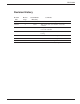
REVISIONS Revision History Revision Date Revised Pages Serial Number Effectivity Comments 09/07/90 All 16231 Issued manual and service parts list, Revision A 10/03/94 4 18354 Tank switch shuts down machine, revised the schematic 05/03/95 4 18629 Changed to new style chemical injection board, revised the schematic 06/07/95 — 18674 Changed to narrow control box, eliminated float rod bearing 02/02/97 All — Reissue of manual and service parts lists, Revision C 02/28/00 39 — Revised w
THIS PAGE INTENTIONALLY LEFT BLANK 2
CONTENTS CONTENTS Page WARRANTY ............................................................................................................................. INTRODUCTION...................................................................................................................... INSTALLATION........................................................................................................................ Unpacking ..............................................................................
WARRANTY LIMITED WARRANTY Champion Industries/Moyer Diebel Limited, P.O. Box 4183, Winston-Salem, North Carolina 27115, and P. O. Box 301, 2674 North Service Road, Jordan Station, Ontario, Canada L0R 1S0 warrants machines, and parts, as set out below.
INTRODUCTION INTRODUCTION Welcome to Moyer Diebel... and thank you for allowing us to take care of your glass washing needs. This manual covers the Model DF glasswashers. Your machine was completely assembled, inspected, and thoroughly tested at our factory before it was shipped to your installation site.
INSTALLATION Unpacking 1. Remove the packing from the top of the conveyor stack. 2. Remove all packing from glass operated switch and right and left trays. Check that the right and left hand trays are positioned properly. 3. Check that the drain deflector is secure in the rinse drain. 4. Check the position of the splash curtain. 5. Check that the conveyor is level and the drive gear is engaged in the conveyor’s outer rim grooves. 6. Remove the packing from within and above the detergent tank. 7.
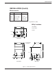
INSTALLATION INSTALLATION (Cont’d) Measurements Uncrated Crated Height 39" (991) 40-1/2"(1181) Width 25-1/4" (640) 27" (685) Depth 25-1/8" (638) 27-1/2" (698) Ship Wt. 154lb/70kg 176lb/80kg *adjustable foot height 1-3/4" (45) max. height 40-3/4" (1035) Utility Locations 1. Hot Water 25 1/4" [641] 2. Cold Water 3.
INSTALLATION INSTALLATION (Cont’d) Electrical Connections 1. The Glass Washer has a six foot power cord with a “U” ground tandem plug for connection to a power receptacle. 2. Provide a nonlocking 250 volt, 15 ampere, 2 pole, 3 wire grounding receptacle within four feet of the base of the Glass Washer(CSA TYPE 6-15R). This should be installed by a qualified electrician to meet the specifications of the local electrical code. 3. This machine operates from 208 to 240 volts.
OPERATION OPERATION General 1. The wash tank is equipped with a float assembly that operates a single camoperated switch. 2. The water temperature is controlled by a heater and a thermostat. The thermostat should be between 140°F/60°C and 160°F/ 71°C. To Fill the Wash Tank B A Figure 3 — Wash Tank Ensure that the standpipe (A) is in place. Put switch (B) to the “ON-FILL” position. The water will fill until the proper level is reached then turn the heating element ON.
OPERATION OPERATION (Cont’d) APPROXIMATE CHEMICAL SETTINGS General Approximate chemical settings can be obtained by counting the revolutions of the injector rotors. 1. For detergent, one revolution per second equals approximately 0.35% concentration. NOTE: Detergent pump only operates when hot water tank is filling. 2. For sanitizer, one revolution in 5 seconds equals approximately 12.5 ppm Iodine or 50 ppm chlorine. 3. For rinse agent, one revolution in 8 seconds is recommended.
OPERATION OPERATION (Cont’d) To Adjust Rinse Agent Injector: 1. When a new rinse agent container is installed, push the prime button in and hold until the rinse injector feed tube is full. 2. Start the washer. Take a sample from the final rinse spray tubes. 3. To increase the volume of rinse agent, turn the adjustment screw clockwise. 4. To decrease the volume of rinse agent, turn the adjustment screw counter-clockwise. NOTE: To meet the requirements of N.S.F.
6 5 Figure 4 — Plumbing Diagram 12 2 3 TO DRAIN WASH 4 1 7 RINSE RINSE 8 9 1) WASH WATER TANK 2) STAND PIPE 3) WASH RETURN SCREEN 4) DRAIN PAN 5) DRAIN SCREEN 6) WASH PUMP SAN DET FLOW 7) MAIN TANK STANDPIPE 8) CHEMICAL INJECTOR 9) INJECTION FITTING 10) WATER INLET VALVES 11) MIXING VALVE 12) VACUUM BREAKER 10 HOT COLD WATER IN WATER IN 11 10 12 OPERATION OPERATION (Cont’d)
MAINTENANCE MAINTENANCE CLEANING Daily Cleaning Instructions 1. Remove the drain tray/waste collector (if installed), from the front of your glasswasher. 2. Turn glasswasher off by flipping the toggle switch located on the wash tank to the “OFF” position. 3. Remove right and left hand trays and splash curtain. Wash them with hot soapy water, rinse thoroughly, then dry. 4.
TROUBLESHOOTING TROUBLESHOOTING 14 CONDITION CAUSE SOLUTION Conveyor does not turn No power.............................................Check fuse panel Turn power switch on Drive motor burnt out .........................Replace Obstruction in wash or rinse ..............Remove obstruction Micro-switch on switch support..........Adjust or replace bracket faulty or not making contact Conveyor not in position.....................
TROUBLESHOOTING CONDITION CAUSE SOLUTION Water temperature low in detergent tank Thermostat setting low........................Adjust thermostat Thermostat defective...........................Replace Defective float switch .........................Replace Heater burnt out ..................................Check and replace Ensure water level is above element Incoming water temp. low ..................Hot water supply min. 145°F/66°C Water on floor around machine Pump seal leaking ....................
THIS PAGE INTENTIONALLY LEFT BLANK 16
REPLACEMENT PARTS REPLACEMENT PARTS 17
REPLACEMENT PARTS 11 10 2 12 13 4 14 15 16 6 17 7 3 8 2 5 1 8 18 36 19 9 35 20 34 21 33 22 32 23 24 31 30 29 28 27 26 Figure 5 — Main Assembly 18 25
REPLACEMENT PARTS MAIN ASSEMBLY Fig. 5 Item No. 1 1 2 2 3 4 5 6 7 8 9 10 11 12 13 14 15 16 17 18 19 20 21 22 23 24 25 26 27 28 29 30 31 32 33 34 35 36 NS NS NS NS Part No.
REPLACEMENT PARTS 4 1 5 3 2 6 10 9 11 8 7 13 14 12 15 16 17 18 19 22 13 21 Figure 6 — Conveyor/Curtain/Switch Assembly 20 20
REPLACEMENT PARTS CONVEYOR/CURTAIN/SWITCH ASSEMBLY Fig. 6 Item No. 1 2 3 4 5 6 7 7 8 8 9 10 11 12 13 14 15 15 16 17 18 19 20 21 22 22 Part No. 0700354 0700997 0501625 0300998 0501538 0501408 0301021 0701128 0707434 0701119 0503810 0307266 0506885 0307322 0501412 0701011 0300848 0706935 0501395 0301012 0501382 0503574 0501483 0503723 0300980 0301008 Part Description Curtain Assembly Complete ...................................................... Curtain Support ............................................
REPLACEMENT PARTS 22 24 21 23 20 25 26 27 28 19 29 17 18 30 16 15 31 14 12 13 11 32 10 33 9 32 8 6 7 1 5 2 4 3 Figure 7 — Control Box 22
REPLACEMENT PARTS CONTROL BOX Fig. 7 Item No. 1 1 2 3 4 5 6 7 8 9 10 11 12 13 14 15 15 15 15 15 16 17 18 19 20 21 22 23 24 25 26 27 28 29 30 31 32 33 Part No.
REPLACEMENT PARTS 8 7 6 5 4 1 2 3 9 10 11 12 13 14 15 16 17 18 20 19 Figure 8 — Control Box Cover/Chemical Injector Board 24
REPLACEMENT PARTS CONTROL BOX COVER/CHEMICAL INJECTOR BOARD Fig. 8 Item No. 1 2 3 4 5 6 7 8 9 9 9 10 10 11 12 13 14 15 16 17 18 19 20 NS NS NS NS Part No. 0508433 106695 0508710 0309037 0503637 0508920 0501450 0501411 0503695 0505483 0503694 0307408 0309052 0503301 0509061 0503343 0300986 0501408 0501538 0307409 0306363 0502666 0501869 0507370 0507578 0509039 0503739 Part Description Circuit Board (starting @ S/N 18629) ....................................... Screw, 6-32 x 1/2"...........................
REPLACEMENT PARTS 2 3 5 4 6 7 8 32 1 33 34 9 10 11 12 26 27 31 13 30 14 15 29 16 28 36 17 18 19 20 35 21 5 22 23 24 25 Figure 9 — Detergent Tank 26
REPLACEMENT PARTS DETERGENT TANK Fig. 9 Item No. 1 1 2 3 4 5 6 7 8 9 10 11 12 13 14 15 16 17 18 19 20 21 22 23 24 25 26 27 28 29 30 31 32 33 34 35 36 Part No. 0707415 0709054 0307379 0307378 0707375 0507471 0700948 0503670 0507426 0703673 0501397 0503701 0505112 0501896 0501600 0503588 0507315 0507323 0501650 0501836 0501419 0707383 0707380 0307423 0503301 0501412 107435 107886 108051 0507431 0502563 0502668 0307427 0503679 0502665 0502662 0502571 Part Description Detergent Tank (up to S/N 18673)........
REPLACEMENT PARTS 8 7 6 8 TO VACUUM BREAKER 7 6 TO DETERGENT TANK 11 3 10 9 1 2 1 3 COLD WATER VALVE 2 4 2 5 3 HOT WATER VALVE 12 13 14 15 16 17 21 18 19 20 22 23 1 25 24 Figure 10 — Inlet Plumbing 28
REPLACEMENT PARTS INLET PLUMBING Fig. 10 Item No. 1 2 3 4 5 6 7 8 9 10 11 12 13 14 15 16 17 18 19 20 21 22 23 24 25 Part No. 0502783 0503802 0503801 0507324 0502768 0502653 0503679 0502665 0509659 0307688 0501419 0504822 0306208 0307373 0501404 0501493 0501533 0505229 0502811 0502810 0502807 0502804 0502803 0501406 0502806 Part Description 230V 60HZ Solenoid Valve ....................................................... 3/8" MPT Tee .........................................................................
REPLACEMENT PARTS 10 9 15 11 12 9 13 14 16 8 7 6 Figure 11 — Sanitizer Plumbing 30 5 4 3 2 1
REPLACEMENT PARTS SANITIZER PLUMBING Fig. 11 Item No. 1 2 3 4 5 6 7 8 9 10 11 12 13 14 15 16 Part No. 0503668 0502583 0502653 0502645 0502666 0300918 0501501 0501539 0502665 0502663 0502652 0503679 0503669 0502781 0507100 0502577 Part Description Thermometer .............................................................................. 3/8" FPT Cross Connector ......................................................... 3/8" MPT x 1/2" 90° Hose Barb ................................................
REPLACEMENT PARTS 4 5 9 6 TO SANITIZER PLUMBING 3 2 1 8 Figure 12 — Vacuum Breaker Plumbing Support 32 7 10
REPLACEMENT PARTS VACUUM BREAKER PLUMBING SUPPORT Fig. 12 Item No. 1 2 3 4 5 6 7 8 9 10 Part No. 0502665 0503679 0502651 0502751 0502650 0502653 0508366 0307391 113220 113221 Part Description 1/2" x 3/4" Inner Braided Tubing .............................................. 7/16" Gear Clamp ...................................................................... 1/2" MPT x 1/2" Hose Barb....................................................... 1/2" Vacuum Breaker (prior to S/N G2147) ...........................
REPLACEMENT PARTS 9 8 8 10 7 5 6 5 4 1 2 3 11 12 13 14 15 17 18 16 Figure 13 — Wash Pump 34
REPLACEMENT PARTS WASH PUMP Fig. 13 Item No. 1 2 3 4 5 6 7 8 9 10 11 12 13 14 15 16 17 18 Part No. 0507313 0307410 0501419 0507320 0502563 0502668 0501632 0503679 0502665 0502663 0502734 0502730 0502729 0502731 0501635 0502732 0503648 0501406 Part Description Wash Pump Complete ................................................................ Wash Pump Base........................................................................ Bolt, 1/4-20 x 1/2" ..........................................................
REPLACEMENT PARTS 8 7 1 6 2 5 4 4 3 Figure 14 — Drive Complete 36
REPLACEMENT PARTS DRIVE COMPLETE Fig. 14 Item No. 1 2 3 4 5 6 7 8 Part No. 0707388 0507145 0307617 0501412 0503574 0501923 0507264 0506886 Part Description Drive Motor Housing Assembly ................................................ Drive Motor................................................................................ Drive Motor Housing Cover ...................................................... Screw, 10-32 x 3/8 .....................................................................
REPLACEMENT PARTS 1 2 3 4 5 6 5 7 8 Figure 15 — Cleaning Accessories 38
REPLACEMENT PARTS CLEANING ACCESSORIES Fig. 15 Part Item No. No. 1 0708986 2 0501826 3 0501633 Part Description Tube Scraper ............................................................................. Tube Brush ................................................................................. Jet Reamer c/w Drill .................................................................. Qty. 1 1 1 OPTIONAL ACCESSORIES (not shown) Fig. 16 Item No. – – – – – – – – – – – – 4 5 6 7 8 Part No.
ELECTRICAL SCHEMATICS RINSE WATER VALVE GLASS SHUTOFF ARM SWITCH CONV. DRIVE MOTOR NO BLACK BLACK WASH PUMP NC ON-OFF SWITCH RED WHITE BLUE MOTOR RED GREEN START CAPACITOR 2.5A FUSE J1 1 2 3 4 5 6 J2 DET PUMP SANI PUMP RINSE PUMP 1 2 3 4 INJECTOR CONTROL BOARD FLUSH TANK FILL TOGGLE SWITCH OFF WASH WATER AUTO VALVE NO WATER LEVEL CAM SWITCH NC HEATER THERMOSTAT DET TANK HEATER FLOAT OPERATED DF M6 0507373 208/230V 12.
ELECTRICAL SCHEMATICS RINSE WATER VALVE GLASS SHUTOFF ARM SWITCH CONV. DRIVE MOTOR NO BLACK BLACK WASH PUMP NC ON-OFF SWITCH RED WHITE BLUE MOTOR RED GREEN START CAPACITOR TANK FILL TOGGLE SWITCH FLUSH OFF AUTO 2.5A FUSE J1 1 2 3 4 5 6 DET PUMP SANI PUMP RINSE PUMP J2 1 2 3 4 INJECTOR CONTROL BOARD FLUSH TANK FILL TOGGLE SWITCH OFF WASH WATER AUTO VALVE NO WATER LEVEL CAM SWITCH NC HEATER THERMOSTAT DET TANK HEATER FLOAT OPERATED DF M6 0507474 208/230V 12.
ELECTRICAL SCHEMATICS RINSE WATER VALVE GLASS SHUTOFF ARM SWITCH CONV. DRIVE MOTOR NO BLACK BLACK NC ON-OFF SWITCH WASH PUMP RED WHITE BLUE MOTOR RED GREEN START CAPACITOR 240V PRIM. TRANSFORMER 18V SEC. RINSE AID PUMP SANITIZER PUMP DET PUMP WHITE POWER INJECTOR CONTROL BOARD DETERGENT 2.