
User Guide


4 | P a g e
EVO ALL Connections
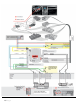
Locate the needed wires in the plugs of the vehicle as shown in the diagram, and connect the
corresponding wires from the EVO-ALL to their respective locations. Cross reference the pin locations
in each plug, and wire colors to verify you are on the right wires in the vehicle. There are 3
connections to make. Match the wires from the T harness up with the 20 pin harness colors as listed
below.
1. Connect the light blue/black wire in the 20-pin plug of the Evo-all to the light blue/black of the
FORT1 T harness.
2. Connect the light blue wire in the 20-pin plug of the Evo-all to the light blue wire of the FORT1
T harness.
3. Connect the yellow wire in the 20-pin plug of the Evo-all to the yellow/black wire of the FORT1
T harness.
4. The yellow wire of the FORT1 T harness is not used, cap the wire off to avoid shorting.
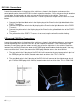
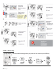
2 Required CAN Wire Connections
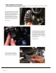
Locate the needed wires in the plugs of the vehicle as shown in the following diagram, and connect
the corresponding wires from the EVO-ALL to their respective locations. Cross reference the pin
locations in each plug, and wire colors to verify you are on the right wires in the vehicle. Route the
loomed Gray and Gray/ Black wire down to the OBDII plug located above the brake pedal. You may
want to remove the 2 screws that mount the OBDII plug to better access the wires behind.
1. The gray wire in the 5-pin plug of the EVO-ALL will connect to the gray/orange wire in pin-3 of
the OBDII plug of the vehicle, located under dash on driver side. This is CAN HI.
2. The gray/black wire in the 5-pin plug of the EVO-ALL will connect to the violet/orange wire in
pin-11 of the OBDII plug of the vehicle, located under dash on driver side. This is CAN LOW.