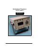
Modulated Precision Clock (MPC) USER MANUAL OM-20000072 Rev 0D
Proprietary Notice Modulated Precision Clock (MPC) User Manual Publication Number: Revision Level: Revision Date: OM-20000072 0D 2002/03/27 Proprietary Notice Information in this document is subject to change without notice and does not represent a commitment on the part of NovAtel Inc. The software described in this document is furnished under a licence agreement or non-disclosure agreement. The software may be used or copied only in accordance with the terms of the agreement.
Table of Contents Proprietary Notice Software License Warranty Policy Customer Service Notices Foreword 2 8 9 10 11 12 Congratulations!.................................................................................................... 12 Scope.................................................................................................................... 12 Prerequisites ......................................................................................................... 12 1 Introduction 13 1.
5.2.2 Connect...................................................................................................44 5.2.3 Configure Client ......................................................................................45 5.2.4 Configure Ethernet..................................................................................46 5.2.5 Configure Modem ...................................................................................47 5.2.6 Configure Direct (PPP) .......................................
Figures 1 2 3 4 5 6 7 8 9 10 11 12 13 14 15 16 17 18 19 20 21 22 23 24 25 26 27 28 29 30 31 32 33 34 35 36 37 38 39 40 41 42 43 44 MPC ................................................................................................................ 13 Typical MPC Setup ......................................................................................... 16 Close-up of Connectors on Rear Panel .......................................................... 19 10 MHz In/Out Data Flow ..........................
45 46 47 48 49 50 51 52 53 54 55 56 57 58 59 60 61 62 63 64 65 66 67 68 69 70 71 72 73 74 75 76 77 78 79 80 81 82 83 84 85 6 Logging Control ...............................................................................................50 Set Up Logging ...............................................................................................51 Command/Response System Summary .........................................................53 Logging Statistics ...............................................
Tables 1 2 3 4 5 6 MPC Controller Models ................................................................................... 14 UDP Message Format ..................................................................................... 52 MPC COM Port Pin-Outs ................................................................................ 79 Latency-Induced Extrapolation Error ............................................................... 86 MPC Power Cable ..................................................
Software License Software License BY OPENING THE SEALED DISK PACKAGE (ENVELOPE), YOU ARE AGREEING TO BE BOUND BY THE TERMS OF THIS AGREEMENT. IF YOU DO NOT AGREE TO THE TERMS OF THIS AGREEMENT, PROMPTLY RETURN THE UNOPENED DISK PACKAGE AND THE ACCOMPANYING ITEMS TO NovAtel Inc. 1. 2. 3. 4. 5. 6. License: NovAtel Inc.
Warranty Policy Warranty Policy NovAtel Inc. warrants that its Global Positioning System (GPS) products are free from defects in materials and workmanship, subject to the conditions set forth below, for the following periods of time: MPC Receiver GPSAntenna™ Series Cables and Accessories Software Support One (1) Year One (1) Year Ninety (90) Days One (1) Year Date of sale shall mean the date of the invoice to the original customer for the product.
Customer Service Customer Service EURO4 FIRMWARE UPDATES AND UPGRADES Firmware updates are firmware revisions to an existing model, which improves basic functionality of the GPS receiver. During the one-year warranty coverage following initial purchase, firmware updates are supplied free of charge. After the warranty has expired, firmware updates and updated manuals may be subject to a nominal charge.
Notices Notices The following notices apply to MPC. CSA NOTICE Each MPC unit has been tested by a Canadian Standards Association (CSA) inspector and found to comply with the special Inspection Requirements of Electrical Equipment. More specifically, this equipment has been tested for Dielectric strength up to 1000 VAC. The supplied AC electric cord is also approved and must be used with this equipment at all times.
Foreword Foreword Congratulations! Congratulations on your purchase of the Modulated Precision Clock (MPC). NovAtel is an industry leader in state-of-the-art GPS receiver design. We believe that our MPC will meet your high expectations, and are working hard to ensure that future products and enhancements will maintain that level of satisfaction. This is your primary hardware and software reference.
Chapter 1 Introduction The MPC is a high performance, high accuracy, GPS receiver with fast data update rates and integrated memory in its hard disk for data logging. The MPC’s front panel also features a Vacuum Fluorescent Display (VFD) panel and keypad for on the fly configurations. Depending on which model you purchase, the MPC is capable of receiving and tracking the L1 C/A code, L1 and L2 carrier phase and L2 P-Code (or encrypted Y-Code) of up to 12 satellites.
Chapter 1 1.1 Introduction Models and Features The MPC is available in several different firmware models whose configurations may include other additional features. Some possible configurations can be seen in Table 1. Table 1: MPC Controller Models Model Name Firmware Feature MPC-L1 L1-only MPC-L1L2 L1/L2 MPC-L1L2W L1/L2 with WAAS a a. Please see Appendix C, WAAS Overview on Page 95.
Introduction 1.2 Chapter 1 ACCESSORIES AND OPTIONS The MPC can be used with the following accessories: • Power cable to connect the MPC to a 110 or 220 VAC power source • An optional choke ring is available for the 501 antenna (model A031) • Optional NovAtel GPSAntenna Model 600 series - dual or single frequency, active antennas designed for high-accuracy applications without the need for a choke ring • Optional NovAtel Model C005, C015, or C030 coaxial antenna cable in 5 m (16.4’), 15 m (49.
Chapter 2 Quick Start Setting up the MPC is a straightforward process, whether you are in the field (collecting data) or back at the office (configuring the MPC, or transferring collected data to your PC for post-processing). CAUTION!: See the cautions on Page 11 of the Notices for a list of items you should be aware of as you set up and use the MPC.
Quick Start Chapter 2 A typical configuration would result from the following steps (see also Figure 2 on Page 16): 1. Place the MPC on a desk or other suitable work surface. 2. Connect the output of a power source to the Power Input port on the back of the MPC. 3. Connect a GPS antenna to the GPS Antenna In connector on the back of the MPC. 4. Connect an appropriate cable from the back of the MPC (PPP, Ethernet or Modem port) to your intended internet or intranet connection source. 5.
Chapter 3 3.1 MPC Setup Considerations Choose the Right Antenna The recommended antenna is from the GPS-600 antenna series, which are ideal for all applications. A Model 600 GPSAntenna provides comparable performance to a choke ring ground plane antenna while being much lighter and smaller. When installing the antenna system, • • choose an antenna location that has a clear view of the sky so that each satellite above the horizon can be tracked without obstruction.
MPC Setup Considerations Chapter 3 CAUTION No warranty is made that the MPC will meet its performance specifications if a non-NovAtel antenna is used. 3.2 Rear Panel Functionality The connections on the rear panel and their connector types are shown on Figure 3. Figure 3: Close-up of Connectors on Rear Panel TNC DB9 RJ45 BNC RJ11 Each connector is keyed to ensure that the cable can be inserted in only one way, to prevent damage to both the MPC and the cables.
Chapter 3 3.2.1 MPC Setup Considerations 10 MHz In and 10 MHz Out There are two BNC connectors on the back of the MPC for 10 MHz In and 10 MHz Out. These two connectors are looped using an RF Loop-Back connector. Therefore by default, the 10 MHz Oven Controlled Crystal Oscillator (OCXO) in the MPC is looped back to the GPS receiver. The GPSCard phase locks to the 5 or 10 MHz reference signal supplied to the rear panel 10 MHz port.
MPC Setup Considerations Chapter 3 device’s. The MPC’s default port settings are [RS232, 9600 BPS, no parity, 8 data bits, 1 stop bit, no handshaking, and echo off]. Changing the default settings can be easily accomplished by means of the COM command (which is described in Volume 2 of the OEM4 Users’ Guide). For information on issuing commands to the MPC via the Modulated Precision Clock website, see List Current Configuration on Page 63.
Chapter 3 3.2.4 MPC Setup Considerations Power After initial connection of the power source to the receiver and pressing the power switch on the back of the unit (see Figure 3 on Page 19), the Power LED on the front of the MPC glows red. The PWR button on the keypad is used to access the MPC Shutdown Type screen in the VFD menus, see Pages 45. Choosing REBOOT will cause the embedded PC to reboot.
MPC Setup Considerations 3.2.5 Chapter 3 RF Port & Cables The GPS Antenna In connector is bi-directional in that it accepts RF signals from the antenna, and it supplies DC power to the low-noise amplifier (LNA) of an active antenna. It has a TNC female connector. Power to this port can be disabled via the ANTENNAPOWER command, refer to Volume 2 of the OEM4 Users’ Guide. The receiver obtains a partially filtered and amplified GPS signal from the antenna via the coaxial cable.
Chapter 3 3.3.1 MPC Setup Considerations I/O Connectors and Cables Below the VFD screen on the front of the MPC are three BNC female connectors: 10 MHz Out, 1PPS Out and Mark In. 3.3.1.1 10 MHz Output The 10 MHz output provides a high-stability reference 10 MHz frequency that is by default phase locked to GPS time. It permits the synchronization of other equipment requiring an extremely stable reference signal of 10 MHz. See also Figure 4 on Page 20.
Chapter 4 Using the MPC Before using MPC for the first time, ensure that you have followed the installation instructions of Chapter 2, Quick Start and Chapter 3, MPC Setup Considerations, starting on Page 16. CAUTION!: See the cautions on Page 11 of the Notice for a list of items you should be aware of as you set up and use the MPC. 4.1 Self-Test When power is applied, it takes several minutes for the computer within the MPC to boot up.
Chapter 4 Using the MPC the menu is changed to ‘YES’, then the IP, SUBNET and GATEWAY rows will be assigned automatically upon activation. Connect an RJ45 cable from your local internet or intranet wall jack to the Ethernet port on the MPC. You may receive an IP address or a “static” IP location on your internal network (intranet) given by your Network Administrator to use as a URL. An IP location associates an IP address with a name, for example “MPC1”, in your Domain Name Server (DNS).
Using the MPC Chapter 4 The Modems Properties dialog will appear as seen in Figure 7. Figure 7: Modems Properties Click on the Add button to install the modem or PPP connection and the Install New Modem dialog will appear as seen in Figure 8. Figure 8: Install New Modem In the Install New Modem dialog, select a modem or direct connection from the list. Insert your operating system install disk into your CD drive (e.g.
Chapter 4 Using the MPC button. The modem installation will continue as seen in Figure 9. Figure 9: Modem Installation Continued Click in the Selected Ports field and select the PC port that your MPC will be connected to from the list. Click on the Next button. Figure 10: Modem Installation Finish Click on the Finish button, see Figure 10, and you will be returned to the Modems Properties dialog, see Figure 11 on Page 29, but you will now see the modem you installed.
Using the MPC Chapter 4 Figure 11: Installed Modem Properties Select your connection in the Modem column and click on the Properties button. Its properties dialog will appear as seen in Figure 12. Figure 12: Connection Properties In the General tab, ensure that the Maximum Speed is set to 115200 to match the MPC.
Chapter 4 Using the MPC OK button. Return to the Control Panel and select the Network icon as seen in Figure 13. Figure 13: Network Icon The Network dialog appears as seen in Figure 14. Figure 14: Network Services Select the Services tab in the Network dialog. Click on the Add button to add a Remote Access Service (RAS) and the Select Network Service dialog will appear as seen in Figure 15 on Page 31.
Using the MPC Chapter 4 Figure 15: Select Network Service Select Remote Access Service and ensure your operating system install disk is in the PC disk drive. Click on the Have Disk button and the Add RAS Device dialog will appear as seen in Figure 16. Figure 16: Add RAS Device Select your connection in the RAS Capable devices field and click on the OK button.
Chapter 4 Using the MPC Figure 18: Network Configuration Check the TCP/IP check box and click in the Allow Any Authentication Including Clear Text field. Click on the Configure button next to the TCP/IP check box and the RAS Server TCP/IP Configuration dialog will appear as seen in Figure 19. Figure 19: RAS Server TCP/IP Configuration Click in the Use This Computer Only field and then the Use Static Address Pool field.
Using the MPC Chapter 4 and End addresses as shown in Figure 19 on Page 32. Click on the OK button and the Remote Access Setup dialog will appear with your connection port, device and type showing as in Figure 20. Figure 20: Remote Access Setup From the taskbar, select Start | Programs | Administrative Tools (Common) | Remote Access Admin, see Figure 21.
Chapter 4 Using the MPC The Remote Access Admin dialog will appear as seen in Figure 22. Figure 22: Remote Access Admin on PC From the main menu, select Server | Start Remote Access Service and the Start Remote Access Service dialog will appear as seen in Figure 23 Figure 23: Start Remote Access Service You may see some service control messages before the Remote Access Admin dialog reappears with your connection status visible, see Figure 24.
Using the MPC Chapter 4 On the taskbar, select Start |Administrative Tools (Common) || User Manager for the User Manager dialog to appear as seen in Figure 25 Figure 25: User Manager From its main menu, select User | New User and the New User dialog will appear as shown in Figure 26.
Chapter 4 Using the MPC Figure 27: Dialin Information Check the Grant Dialin Permission to User check box and click in the No Call Back field. Click on the OK button. Restart your PC for the new settings to take effect. Ensure your MPC is powered on. At the MPC VFD screen, use the navigation button to go to the CONFIG DIRECT, or CONFIG MODEM, menu. Set up a client as described in Section 5.2.3, Configure Client on Page 45.
Using the MPC Chapter 4 Change the DIRECT row status to CONNECT:YES. Once you have pressed the ENTER key, the MPC will attempt to ‘dial in’ to the host computer. If successful, the IP address will appear in the DSTATUS row if there are no errors, and an error message will appear if there is an error. Open your internet browser and type in the IP address shown in the DSTATUS row as the URL. If successful, you should see the loading screen as shown in Figure 30.
Chapter 4 Using the MPC Ì Î Ï Í CONFIG CLIENT USRNAME ABCDEFG PASSWRD TUVWXYZ ADMIN PRIV:NO LOGGING CONTROL:NO FTP ACCESS:NO STATUS VIEW:NO SUBMIT INFO:NO Figure 32: CONFIG CLIENT Menu You can add\edit users and their privileges by choosing Setup in the Modulated Precision Clock home page followed by the Set Up Users button. See also Section 6.1.2.7, Set Up Users on Page 65. Details on the Modulated Precision Clock website login and features can be found in Section 6.1 starting on Page 49.
Using the MPC Chapter 4 a data link capable of data throughput at a rate of 2400 bits per second or higher is sufficient for the examples shown below. The external device is connected to the MPC’s DGPS port with a usersupplied RS232 cable. Pre-configure the MPC as a base station via the Modulated Precision Clock website, see Set Up Base Station on Page 63 for details.
Chapter 5 VFD Menus The front panel of MPC has a Vacuum Fluorescent Display (VFD) with 7 interaction keys. The panel consist of four navigational, a combination edit/enter, a power, and an escape key. The main functions of the VFD menu are: • MPC Status • MPC Connect • Configure Client • Configure Ethernet • Configure Modem • Configure Direct (PPP) Accompanying this manual is a water/tear proof VFD Menus Quick Look Guide for on the fly referencing of menu locations.
VFD Menus Chapter 5 where you can access any of the main functionality menus and their columns. MPC SYSTEM STATUS Ì Î Ï Í TIME 12:33:24 GMT GPS DATE 1143 W 493408 S GPS GPS SYSTEM OK EXT OSC LOCKED LOGGING NOT ACTIVE SPACE 935840 KB COMPUTER TEST_9 Figure 34: Opening Menu 5.1 Menu Access The menu structure is arranged as columns of functionality. Each column may have several pages of related data where a page can have up to seven rows.
Chapter 5 VFD Menus group in an editable row to be underlined. The left and right arrows move the cursor to the groups in the row. The up and down arrows cycle through a list of choices for that group value. An example of a group value that the cursor has been moved to, is the PPP value shown in Figure 36. Press the key to return you to the top of the menu and save the new group value. Ì Î Ï Í CONFIG MODEM PHONE 1.900.244.
VFD Menus Chapter 5 The information in this column is refreshed every second unless another column in the menus is being edited. The 1 second refresh will continue once the editing has stopped. As seen from Figure 37 on Page 42, there are several STATUS functionality categories: • MPC SYSTEM STATUS • TIME: The current GMT time in hours, minutes and seconds. The time is the PC time, which is steered by GPS.
Chapter 5 VFD Menus • LON: The current longitude in degrees, minutes, seconds and decimal seconds to 4 decimal places. • HEIGHT: The current mean sea level (MSL) height in meters to 3 decimal places. • # SATS: The number of GPS satellites currently being tracked. • MPC RECEIVER INFO • SERIAL #: The GPSCard serial number. • VERSION: The GPSCard firmware version. • MODEL: The GPSCard model. • UI VER: Shows the current version of the VFD user interface software. 5.2.
VFD Menus Chapter 5 • MODEM: CONNECT: YES or NO depending on whether there is or is not respectively a connection via the modem card. • MSTATUS: The IP address of the modem connection or a status message. • DIRECT: CONNECT: YES or NO depending on whether there is or is not respectively a connection via the serial port. • DSTATUS: The IP address of the direct connection or a status message. The MSTATUS and DSTATUS rows are refreshed when the Remote Access Service (RAS) calls back.
Chapter 5 VFD Menus maximum). The MPC allows multiple users. Example of clients may be the administrator who has all privileges, the users who have some but not all privileges, and guests who have little or no privileges. • PASSWRD: A password for the above user (8 characters maximum). • ADMIN: ‘YES’ or ‘NO’ depending on whether this user has or has not respectively system privileges. • LOGGING: ‘YES’ or ‘NO’ depending on whether this user has or has not respectively the right to control logging.
VFD Menus Chapter 5 directly with each other. • GATEWAY: The address of the device that will transfer messages out of the local network to the internet. • COMPUTER: Give your MPC a network name (8 characters maximum). 5.2.5 Configure Modem The CONFIG MODEM functionality group allows you to configure the internal modem connection with the MPC. Figure 41 on Page 47 shows the CONFIG MODEM menus.
Chapter 5 VFD Menus • CFG MODEM HOST The MPC modem is preconfigured for auto-answering as a host. It will issue an IP address in the range 192.160.200 to 192.160.215, and establish a PPP connection to the client. The client must use an Administrator username and password or set up a user, see also Section 5.2.3, Configure Client on Page 45. • ASSIGN: ‘YES’ or ‘NO’ depending on whether or not respectively the IP start and stop addresses are assigned automatically.
Chapter 6 Software Programs The MPC software for the Euro4 GPSCard and the VFD are already installed. The Modulated Precision Clock website is accessible on a PC via an internet connection. It is your source for MPC setup, logging, system summaries and analysis plots. Details are given in Section 6.1, Modulated Precision Clock Website starting below. Please see Section 6.2, MPC Firmware Upgrades & Updates starting on Page 75 for a description on how your MPC is upgraded/updated via the web.
Chapter 6 Software Programs As seen from Figure 43 on Page 49, there are four options in the Modulated Precision Clock home page: Logging, see Section 6.1.1, Logging below Setup, see Section 6.1.2, Setup Configuration on Page 55 Analysis Plots, see Section 6.1.3, Analysis Plots on Page 67 Download Data, see Section 6.1.4, Download Data on Page 72 Once you are on the Modulated Precision Clock web page, you can type in your user ID and password, and click on the OK button to log in.
Software Programs 6.1.1.1 Chapter 6 Logging Setup You can set up logs for up to 5 channels on your MPC. Select a channel and click on its button, see Figure 46. support@novatel.ca a Figure 46: Set Up Logging First, choose where to send your data. If you select Log to File, give your schedule for that channel a name in the First Characters of File Name field. If this field is left blank, the schedule for that channel will be ignored.
Chapter 6 Software Programs Table 2: UDP Message Format Description Offset Size Type Value Sync1 0 1 uchar 0xAA Sync2 1 1 uchar 0x44 Sync3 2 1 uchar 0x16 MPCID 3 4 ulong 0....MAX_ULONG (unique MPC station ID, see Section 6.1.2.1, Set MPC Name on Page 56) Hop Count 7 1 uchar 0...255 (the number of times the UDP was forwarded between NovAtel relay stations) Message Length 8 2 ushort 0...
Software Programs 6.1.1.2 Chapter 6 Parsing Responses Click on the Parsing Responses button to go to the Command/Response System Summary window as seen in Figure 47.
Chapter 6 Software Programs There are three types of output in the summary: Cmd Res A log summary in the form: Cmd: YYYY-MM-DD hh:mm:ss.ss>LOG THISPORT_c log where YYYY is the calendar year (e.g. 2002) MM is the calendar month (01-12) DD is the calendar date (01-31) hh.mm.ss.ss is the time in hours (00-23), minutes (00-59) and decimal seconds (00.00-59.
Software Programs 6.1.1.3 Chapter 6 Logging Stats In the Logging Control window, click on the Logging Stats button to bring you to the Logging Statistics page. An example is shown in Figure 48. Figure 48: Logging Statistics Choose a Channel by clicking on its button. Log summaries are shown line by line.
Chapter 6 Software Programs Figure 49: Set Up Configuration 6.1.2.1 Set MPC Name Click on the General Setup button for the Modify Receiver Parameters window to appear as seen in Figure 50 on Page 56. Figure 50: General Receiver Setup The Receiver Name is a name you give your MPC that is meaningful to you. This name will also appear in the main Modulated Precision Clock windows (Logging, System Summary Response, Setup and Analysis Plots).
Software Programs Chapter 6 ID number which is imbedded in the UDP data stream (if used), see Section 6.1.1.1, Logging Setup on Page 51. It uniquely identifies the messages as originating from your MPC. Click on the Go button to save your changes. 6.1.2.2 Set Up E-Mail Server If you intend to transfer collected data files via an e-mail attachment, you must set up e-mail server information through The Set Up E-Mail Server page as seen in Figure 51.
Chapter 6 Software Programs Figure 52: Disk Maintenance Click on the Set Auto Cleanup Values button to save your selection, or click on the Cancel button to disregard your changes and return you to the main Configuration Setup window. Click on the Delete Files button and the Delete Files window will appear as seen in Figure 53. Figure 53: Delete Files The *.log checkboxes in the top half of the dialog allow you to select log files for deletion.
Software Programs Chapter 6 Service if you have any MPC questions or problems. Files that become too large can be selected here and then deleted by clicking on the Delete System Log Files button. The bottom half of the Delete Files dialog allows you to choose a week number by clicking on one of the available GPS weeks button. If you need to refer to a calendar of GPS weeks, click on the GPS Calendar button first. A description of the GPS Calendar is given in Section 6.1.4, Download Data on Page 72.
Chapter 6 Software Programs CONFIGURE PPP PORT An example of the Configure PPP Port window is shown in Figure 56. Figure 56: Configure PPP Port First enter the user name and password the MPC will use to ‘connect’ to the PPP host in the User Name and Password fields. Then enter the number of redial attempts you would like the MPC to make and choose a length of time between these attempts. Choose how long, or never, to wait while the connection is idle before the MPC should hang up.
Software Programs Chapter 6 CONFIGURE MODEM PORT An example of the Configure Modem Port window is shown in Figure 57. MPC1 12MPC34 2954500 Figure 57: Configure Modem Port First enter the user name and password the MPC will use to ‘connect’ to the PPP host in the User Name and Password fields. Then enter the phone number that the modem is to call out on to make a connection with the host or internet service provider.
Chapter 6 Software Programs CONFIGURE ETHERNET PORT An example of the Configure Ethernet Port window is shown in Figure 58. Figure 58: Configure Ethernet Port Select whether to enter the IP address for the modem connection in the Set IP field, or select Obtain an IP Automatically for the IP address to be assigned automatically.
Software Programs Chapter 6 SET UP BASE STATION To set up your MPC as a base station, click on the Set Up Base Station button in the Receiver Setup dialog, see Figure 59, to bring you to the List Current Configuration window where you can enter GPS commands. See also List Current Configuration starting on Page 63. To fix the position for your MPC base, enter the Latitude, Longitude and Height using the FIX command. If you do not fix the base station position, the current position is computed by the MPC.
Chapter 6 Software Programs Chapter 1 Used by MPC’s internal Euro4 receiver - do not adjust! Used by MPC’s internal 10 MHz OCXO - do not adjust! MPC status messages to COM1.
Software Programs 6.1.2.6 Chapter 6 Reload Firmware In the Setup Configuration dialog, see Figure 49 on Page 56, click on the ReLoad Firmware button to bring you to the screen shown in Figure 61. Figure 61: Reload Firmware WARNING: The Reload Firmware page is intended for use by NovAtel Customer Service personnel only. Incorrect commands on this page may result in the MPC being permanently disabled! For more information on firmware or PC software upgrades/updates please see Section 6.
Chapter 6 Software Programs SELECT USER TO EDIT Click on the Edit button in the Set Up Users window and the Edit User window will appear as seen in Figure 63. Figure 63: Edit User Check in the privileges check boxes that apply to the current user.
Software Programs Chapter 6 Enter a username and password for the new user. Then re-enter the password in the Re Enter Password field to ensure you typed it in correctly. Click on the Submit New User field to save the new user, or on the Home button to disregard your changes and return to the main Set Up Users page. 6.1.3 Analysis Plots The Analysis Plots Page gives you a choice of multiple plots in two formats.
Chapter 6 Software Programs Figure 66: Choose Value to Plot Against Time The default plot shown is the Temperature Vs. Time plot over 5 minutes. Select a value to plot against time in the Choose Value to Plot field. Your choices are: • Temperature • GDOP • OEM4 Idle Time • Number of Satellites • Clock Error • Clock Steering Next choose the time period for your plot. The choices range from 5 minutes up to a maximum of 10 years. Click on the GO button to generate the plot. An example of a Temperature Vs.
Software Programs Chapter 6 Figure 67: Time Plot Example Figure 68 shows the key that is displayed with each plot. It is a key of how the points in the plot are portrayed. Figure 68: Time Plot Key All plots are displayed in *.PNG format. 6.1.3.2 Sky Plots When you click on the Sky Plots icon in the Analysis Plots screen, see Figure 65 on Page 67, a dialog appears with fields that allows you to select a sky plot of your choice and the time period for the plot. The fields are shown in Figure 69 below.
Chapter 6 Software Programs Next choose the time period for your plot. The choices range from 1 hour up to a maximum of 7 days. Click on the GO button to generate the plot. In the Constellation plots, each colour represents a satellite PRN. An example is shown in Figure 70. Figure 70: Constellation Sky Plot In the Carrier to Noise, and Code Minus Carrier, versus Elevation plots, each colour represents the minimum, maximum and mean values of the data.
Software Programs Chapter 6 Figure 71: L1 Carrier to Noise Vs. Elevation Figure 72: L2 Code Minus Carrier Vs.
Chapter 6 6.1.4 Software Programs Download Data In the Logging Control window, click on the Download Data button. The Download Files window appears as seen in Figure 73. Figure 73: Download Data You are shown a choice of GPS week buttons. You can first use the GPS Calendar button to check which GPS week you are interested in. The GPS Calendar window can be seen in Figure 74 on Page 72.
Software Programs Chapter 6 Each GPS week is shown in the far left of the screen. There are also three rows for each GPS week that show: date The regular calendar dates for the week ydate Each corresponding number of days into the year for each day of the week mjd The Modified Julian Day (MJF) is defined as the Julian Day minus 2400000.5. For any date in the 20th and 21st centuries, the MJD will be at most five decimal digits long.
Chapter 6 Software Programs Figure 76: Typical File Download Window To save the file to disk, choose the Save This File to Disk field. Click on the OK button and a Save As window appears (Figure 77) so that you can browse for a location for the file and save the file as a different filename if you choose. Figure 77: Save As The Save As window is shown in Figure 77. Click on the Save button to save the file in your chosen location.
Software Programs 6.2 Chapter 6 MPC Firmware Upgrades & Updates The MPC includes two distinct processors in its enclosure: • a GPS receiver (Euro4 GPSCard) • an embedded PC running embedded NT Both of these components has its own microprocessor, and each microprocessor has its own firmware (program software), which is stored in non-volatile memory. What makes one MPC model different from another is software, not hardware.
Appendix A A.1 Technical Specifications MPC Performance Position Accuracy a Standalone: L1 only L1/L2 1.8 m CEP 1.5 m CEP WAAS: L1 only L1/L2 1.2 m CEP 0.8 m CEP Code Differential 0.45 m CEP Post Processed 5 mm + 1 ppm CEP Time To First Fix 15 minutes (due to OCXO warm-up) Reacquisition 0.5 s L1 (typical) 6 s L2 (typical) Data Rates Raw Measurements: Computed Position: 20 Hz C/A code phase 6 cm RMS Measurement Precision 20 Hz L1 carrier phase: Differential 0.
Technical Specifications A.2 Appendix A MPC Specifications MPC CARDS There are 5 cards in the MPC Euro4 GPS, Computer, Clock, Power, and Modem INPUT/OUTPUT CONNECTORS GPS Antenna Input TNC female jack, 50 Ω nominal impedance +4.25 to +5.25 V DC, 90 mA max (output from MPC to antenna/LNA) Frequency: L1(1575.42 MHz), L2 (1227.6 MHz) Power Input 3-pin A/C chord provided (for North American Standard A/C) Voltage: 100 to 240 VAC Frequency: 50 to 60 Hz Warm-up power: 34 W Typical power: 30 W Fuse: 1.
Appendix A Technical Specifications BACK PANEL 10 MHZ IN Connector BNC female Capture range 5 or 10 MHz ± 5 Hz Sensitivity +9 dBm to +20 dBm into 50 Ω FRONT PANEL 10 MHZ OUT Short Term Stability (Allen Variance) ±1 x 10-12, 1 day RF Output Power 10 ± 3 dBm into 50 Ω Output Waveform Harmonics: Spurious: Sine wave -15 dBc -80 dBc Phase Noise @10 Hz: @100 Hz: @1 kHz: RF Output Connector BNC Female -125 dBc/Hz -155 dBc/Hz -165 dBc/Hz FRONT PANEL 1PPS OUT Connector BNC Female Signal Descript
Technical Specifications A.3 Appendix A Port Pin-Outs Table 3: MPC COM Port Pin-Outs PPP DGPS RS232 RS232 1 N/C N/C 2 RXD RXD 3 TXD TXD 4 N/C N/C 5 GND GND 6 N/C N/C 7 RTS RTS 8 CTS CTS 9 N/C N/C Connector Pin No.
Appendix A A.4 Technical Specifications Power Cable The power cable supplied with the MPC, connects from the Power Input port on the back of the MPC to an external power source (100 to 240 VAC). An input voltage of less than 100 VAC will cause the unit to suspend operation while an input voltage greater than 240 VAC may physically damage the unit, voiding the warranty.
Appendix B GPS Overview The Global Positioning System (GPS) is a satellite navigation system capable of providing a highly accurate, continuous global navigation service independent of other positioning aids. GPS provides 24-hour, all-weather, worldwide coverage with position, velocity and timing information.
Appendix B GPS Overview receiver with at least six satellites in view from any point on earth, at any particular time. The GPS satellite signal identifies the satellite and provides the positioning, timing, ranging data, satellite status and the corrected ephemerides (orbit parameters) of the satellite to the users. The satellites can be identified either by the Space Vehicle Number (SVN) or the Pseudorandom Code Number (PRN). The PRN is used by the NovAtel GPSCard.
GPS Overview Appendix B Figure 80: Illustration of GPSCard Height Measurements References: 1 Topography 2 Geoid (mean sea level) 3 Spheroid (ellipsoid) H = GPSCard computed height above/below geoid N = Geoidal Height (undulation) h = GPS system computed height above the spheroid N=h-H From the above diagram, and the formula h = H + N, to convert heights between the ellipsoid and geoid we require the geoid-ellipsoid separation value. This value is not easy to determine.
Appendix B GPS Overview hairs, the centre of the shaded area is the "location" of the mean estimate, and the radius of the shaded area is a measure of the uncertainty contained in the estimate. Figure 81: Accuracy versus Precision1 B.3.1 High accuracy, high precision Low accuracy, high precision High accuracy, low precision Low accuracy, low precision Single-Point vs.
GPS Overview Appendix B positioning requires either a data link between the two stations (if the positioning is to be achieved in real-time) or else post-processing of the data collected by the remote station. At least four GPS satellites in view are still required. The absolute accuracy of the remote station’s computed position will depend on the accuracy of the reference station’s position.
Appendix B B.4 GPS Overview Differential Positioning There are two types of differential positioning algorithms: pseudorange and carrier phase. In both of these approaches, the “quality” of the positioning solution generally increases with the number of satellites which can be simultaneously viewed by both the reference and remote station receivers.
GPS Overview B.5 Appendix B Pseudorange Algorithms Pseudorange algorithms correlate the pseudorandom code on the GPS signal received from a particular satellite, with a version generated within the reference station receiver itself. The time delay between the two versions, multiplied by the speed of light, yields the pseudorange (so called because it contains several errors) between the reference station and that particular satellite.
Appendix B • • GPS Overview effectively cancel the receiver clock offset bias. Thus, in single-point positioning, receiver clock offset is not a significant problem. However, in pseudorange differential operation, between-receiver clock offset is a source of uncorrelated bias.
GPS Overview B.5.1.2 Appendix B Single-Point Averaging with the GPSCard By averaging many GPS measurement epochs over several hours, it is possible to achieve a more accurate absolute position. This section attempts to explain how the position averaging function operates and to provide an indication of the level of accuracy that can be expected versus total averaging time. The POSAVE command implements position averaging for reference stations.
Appendix B GPS Overview Figure 83: Single-Point Averaging * This graph represents typical results using position averaging. 35 30 Standard Deviation (meters) 25 20 15 10 5 0 0 4 8 12 16 20 24 28 32 36 40 44 48 Time (hours) Latitude Longtitude Height This function is useful for obtaining the WGS84 position of a point to a reasonable accuracy without having to implement differential GPS.
GPS Overview B.5.2 Appendix B Dual Station Differential Positioning It is the objective of operating in differential mode to either eliminate or greatly reduce most of the errors introduced by the above types of system biases. Pseudorange differential positioning is quite effective in removing most of the biases caused by satellite clock error, ionospheric and tropospheric delays (for baselines less than 50 km), ephemeris prediction errors, and SA.
Appendix B B.5.2.1 GPS Overview The Reference Station The nucleus of the differential network is the reference station. To function as a reference station, the GPS receiver antenna must be positioned at a control point whose position is precisely known in the GPS reference frame. Typically, the fixed position will be that of a geodetic marker or a pre-surveyed point of known accuracy.
GPS Overview B.6 Appendix B Carrier-Phase Algorithms Carrier-phase algorithms monitor the actual carrier wave itself. These algorithms are the ones used in real-time kinematic (RTK) positioning solutions - differential systems in which the remote station, possibly in motion, requires reference-station observation data in real-time. Compared to pseudorange algorithms, much more accurate position solutions can be achieved: carrier-based algorithms can achieve accuracies of 1-2 cm (CEP).
Appendix B GPS Overview searching process can more rapidly and accurately home in on the correct lane when dual-frequency measurements are available. Changes in the geometry of the satellites aids in ambiguity resolution; this is especially noticeable in L1-only solutions. In summary, NovAtel’s RTK system permits L1/L2 receivers to choose integer lanes while forcing L1-only receivers to rely exclusively on the floating ambiguity solution.
Appendix C WAAS Overview The Wide Area Augmentation System (WAAS) is a safety-critical system that provides a quality of positioning information previously unavailable. The WAAS improves the accuracy, integrity, and availability of the basic GPS signals. In the future, the wide area of coverage for this system will include the entire United States and some outlying areas.
Appendix C WAAS Overview Geostationary Satellite (GEO) L1 GPS Satellite Constellation L1 & L2 L1 & C-band Integrity data, differential corrections, and ranging control GPS User C-band Wide-area Reference Station (WRS) Wide-area Reference Station (WRS) Wide-area Master Station (WMS) Wide-area Reference Station (WRS) Ground Uplink Station (GUS) Integrity data, differential corrections, time control, and status Figure 85: The WAAS Concept C.
Appendix D Replacement Parts The following are a list of the replacement parts available for your NovAtel GPS receiver. Should you require assistance or need to order additional components, please contact your local NovAtel dealer or Customer Service representative.
Index 10 MHz in/out, 20, 1PPS, 24 24 patch RJ45, 21 power, 80 warranty, 9 calendar, 72 carrier-phase, 86 carrying handle, 14 cautions, 11, 19 client configure, 36, 45, 47–48 connect, 26–36 clock bias, 84, 93 data, 82 external, 20 offset, 88 synchronization, 87 CMR, 63 coaxial cable, 18, 23, 97 COM ports, 79 commands enter, 55 OEM4 Users’ Guide, 97 position averaging, 89 pre-configuring, 39 summary, 52–54 communications cable, 20 configuration, 14, 17 base, 55, 63 differential, 91 factory, 18 internet, 17,
Index DC, 23, 77 dealer, 10 DGPS, 20, 38 differential corrections, 89, 91–92 operation, 14 positioning, 84, 86–87, 91 dilution of precision (DOP), 86, 88 distance, 93 download data, 72–74 E elevation, 93 e-mail, 10 ENTER key, 23, 41, 43–44 ephemeris errors, 87, 91 overview, 82 errors, 39 ephemeris, 87 in single-point positioning, ESC key, 23, 41, 43–44 Ethernet, 21, 25–26 extended cable lengths, 18 external clock, 20 F factory, 18 features, 14 filename, 51 firmware, 10, 14, 75 fix position, 63 fixed ambig
Index navigation, 81 NAVSTAR satellites, 81 network configuration, 25–38 I/O, 21 noise, 87, 93 notices, 11 NovAtel Inc.
Index T TCXO, see oscillators technical specifications, 76–77, temperature, 77 time to first fix (TTFF), 76 tracking loops, 93 trigger event, 24 tropospheric, 87, 91 79–80 U upgrades and updates, 10, 65, 75 V velocity, 81–82 VFD panel, 25, 40 configure, 45 connect, 44 direct, 48 ethernet, 46 logging, 45 menu access, 41 modem, 47 power down, 44 PPP, 48 status, 42–44 voltage, 22 Volume 2, OEM4 Users’ Guide, 97 W WAAS, 95 warning, 63, 65 warnings, 19, 22 warranty, 8–10, 19 website, 10, 49–50 weight, 77
OM-20000072 Rev 0D 2002/03/27