Host Print Set-up Guide D60425-06 November 2007 MPI Tech A/S Vadstrupvej 35 2880 Bagsvaerd Denmark Tel: +45 44 36 60 00 Fax: +45 44 36 61 11 www.mpitech.
Table of contents 1 PSF/MVS AFP Printing Using TCP/IP ..................................................3 1.1 PSF/MVS direct attachment ..............................................................3 1.2 PSF/MVS start-up procedure .............................................................3 2 z/OS SCS Printing Using TN3270e ......................................................5 2.1 TN3270E Setup using z/OS Communication Server ..............................5 2.1.
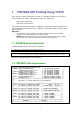
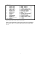
1 PSF/MVS AFP Printing Using TCP/IP This chapter provides information on how to create MVS definitions for printing from PSF/MVS via TCP/IP. The following topics are addressed: JES printer statements PSF Start-up procedure Once these parameters have been configured, and the basic TCP/IP installation of the PrintServer with IPDS has been completed, direct AFP / IPDS from PSF / MVS will be possible.
//PRT420 //PRT420 // // // // // // // // // // // // // // // // // // // // // //PRT420 CNTL PRINTDEV FONTDD=*.FONT01, OVLYDD=*.OLAY01, PSEGDD=*.PSEG01, PDEFDD=*.PDEF01, FDEFDD=*.FDEF01, JOBHDR=*.JOBHDR, JOBTRLR=*.JOBTLR, DSHDR=*.DSHDR, MESSAGE=*.MSGDS, PAGEDEF=A06462, FORMDEF=A10110, CHARS=(GT10, GT12,GT15,GT10), PIMSG=YES, DATACK=BLOCK, TRACE=NO, FAILURE=WCONNECT, TIMEOUT=REDRIVE, DISCINTV=0, MGMTMODE=IMMED, IPADDR=‘192.0.110.
2 z/OS SCS Printing Using TN3270e This chapter provides examples of how to set up SCS printing using TN3270e. 2.1 TN3270E Setup using z/OS Communication Server The IBM z/OS is capable of supporting TN3270e sessions communicating directly. The following describes the required mainframe definitions for a LinkCom or DocOut. It is assumed that the TN3270e service is already active on the mainframe. 2.1.
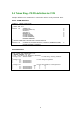
3 Mainframe Printing Using SNA This chapter provides: Note: The descriptions below appear in Ethernet and Token Ring versions respectively, and the sections are marked accordingly. Be sure to select the right section. • sample LU1 printer logmode definitions: 3.1 Logmode • sample definitions for installation in association with a locally attached 3174 and 3745: 3.2 Ethernet - PS PU definition for 3174 3.3 Ethernet - PS PU definition for 3745 3.4 Token Ring - PS PU definition for 3174 3.
3.2 Ethernet - PS PU definition for 3174 Sample definition for installation in association with a locally attached 3174.
PrintServer Definition file extract &&??##N1,0# ; Start of file - Don't remove this ! ;-----------------------------------------------------------------------; Configuration for the Ethernet PrintServer ; (This is an example. Please modify the parameters to match ; your configuration).
PU/LU Definitions SPPRKEN * PA01B91 * B91PATH * TA01B911 * VBUILD TYPE=SWNET, SWITCHED MAJOR NODE MAXNO=1, MAXGRP=1 STATOPT=‘NN PRINTER’ PU ADDR=C1, IDBLK=017, IDNUM=E2961, DISCNT=NO, MAXOUT=1, MAXDATA=1033, MODETAB=MTABPS, PACING=3, VPACING=3, MAXPATH=1, PUTYPE=2, DLOGMOD=MODPS PATH DIALNO=020400036E0035C9,GRPNM=ZTOKEN,GID=1,PID=1 LU LOCADDR=2,DLOGMOD=MODPS PSF JCL //PRTN //PRTN // // // // // // // // // // // CNTL PRINTDEV FONTDD=*.FONT300, OVLYDD=*.OLAY01, PSEGDD=*.PSEG01, PDEFDD=*.PDEF01, FDEFDD=*.
3.4 Token Ring - PS PU definition for 3174 Sample definition for installation in association with a locally attached 3174.
PrintServer Definition file extract &&??##N1,0# ; Start of file - Don't remove this ! ;-----------------------------------------------------------------------; Configuration for the Token Ring PrintServer ; (This is an example. Please modify the parameters to match ; your configuration).
PU/LU Definitions SPPRKEN * PA01B91 * B91PATH * TA01B911 * VBUILD TYPE=SWNET, SWITCHED MAJOR NODE MAXNO=1, MAXGRP=1 STATOPT=‘NN PRINTER’ PU ADDR=C1, IDBLK=017, IDNUM=E2961, DISCNT=NO, MAXOUT=1, MAXDATA=1033, MODETAB=MTABPS, PACING=3, VPACING=3, MAXPATH=1, PUTYPE=2, DLOGMOD=MODPS PATH DIALNO=020400036E0035C9,GRPNM=ZTOKEN,GID=1,PID=1 LU LOCADDR=2,DLOGMOD=MODPS PSF JCL //PRTN CNTL //PRTN PRINTDEV FONTDD=*.FONT300, /*FONT LIBRARY DD */ // OVLYDD=*.OLAY01, /*OVERLAY LIBRARY DD */ // PSEGDD=*.
4 Configuration of MS SNA/HIS Server This chapter provides examples of how to set up SCS printing using TN3270e. 4.1 General setup 4.1.1 Adding DLC 802.2 protocol to your Windows Server / Workstation In order to communicate via Token ring or Ethernet over SNA, you must add the DLC protocol to your Windows Server or Workstation running SNA Server.
4.1.2 SNA Server configuration – Create a link You must define the Server LAN card to be used to communicate with the host. - Folder Link Services, make a right click and select Link Service. Select DLC 802.2 Link Service from the list. - In the DLC 802.2 Link Service Properties window, select the LAN card you want to use. 4.1.
Connections : General Connections : Address Note : Remote Network Address must match the Host MAC Address (TIC) 15
Connections : System Identification Note : local Node ID must match the ID_NUM and ID_BLOCK parameters of the VTAM PU Definition Connections : System Identification Note : MAX BTU Length must match the MAX_DATAD parameter of the VTAM PU Definition 16
4.2 SNA Server configuration – Create a Printer LU Attached to the connection, you must create your printer LU. In order to run with MPI Router, you must define a LUA LU. - Make a right click on your connection and select Application LU (LUA).
4.3 Configuring BlueServer for SNA communication 4.3.1 Setup Connection tab Notes: - The other tabs “IPDS Settings”, “Paper Controls”, are not used in this case. - The SCS Settings tab is only used only for SCS printout.
4.4 Loading the Router Mainframe and Parser 4.4.1 Microsoft SNA/HIS status indication The PSNA201 is SSCP 4.4.2 Blue Server status indication With this configuration, you are now able to print SCS or IPDS jobs from your Mainframe IBM host.
4.5 Configuring DocOut for SNA communication 4.5.
4.5.2 Microsoft SNA/HIS status indication The PSNA201 is SSCP 4.5.3 DocOut status indication With this configuration, you are now able to print SCS or IPDS jobs from your Mainframe IBM host.
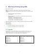
5 PSF/AIX IPDS Printing Using TCP/IP This chapter provides details on: Adding a TCP/IP attached printer Set up of the KEEPALIVE TCP/IP feature The basic TCP/IP installation of the PrintServer (IPDS) must be completed before direct AFP / IPDS from PSF/AIX will be possible. 5.1 Adding TCP/IP attached printer The port number is defined in the PSF/AIX SMIT Add a TCP/IP-Attached Printer panel. 1. Enter Printer name PSF/AIX uses the printer name you specify. Enter a name of up to 8 characters. 2.
5.3 AIX KEEPALIVE support The no (network options) command can be used by the root user to configure KEEPALIVE frequencies. no -o tcp_keepidle=nnn no -o tcp_keepintvl=nnn when nnn is in half-seconds. The command tcp_keepidle specifies the interval of inactivity causing the TCP to generate a KEEPALIVE transmission for an application that requests them. The default is 14400 (2 hours).
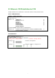
6 PSF/400 AFP Printing Using TCP/IP This chapter provides configuration guidelines for AS/400 IPDS Printing over TCI/IP. These guidelines are applicable for OS/400 version 3.7, 4.X and 5.X. The examples of completed screens given are for OS/400 version 4.X and 5.X and may contain some additional parameters not seen in version 3.7, these may be ignored.
A completed PSF Configuration looks like this: PSF Configuration Information PSF configuration: NETWRKPRT User resource library . . . . IPDS pass through . . . . . . Activate release timer. . . . Release timer . . . . . . . . Restart timer . . . . . . . . SNA retry count . . . . . . . Delay time between retries. . Blank page. . . . . . . . . . Page size control . . . . . . Resident fonts. . . . . . . . Resource retention. . . . . . Edge orient . . . . . . . . . Remote location: Name or address . . . . . . .
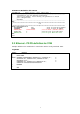
Display Device Description Page 1 5716SS1 V4R4M0 981108 BLDRB1 09/11/98 12:02:59 Device description . . . . . . . . : DEVD Option . . . . . . . . . . . . . . : OPTION *ALL Category of device . . . . . . . . : *PRT Device class . . . . . . . . . . . : DEVCLS *LAN Device type. . . . . . . . . . . . : TYPE *IPDS Device model . . . . . . . . . . . : MODEL 0 LAN attachment . . . . . . . . . . : LANATTACH *IP User-defined object . . . . . . . : USRDFNOBJ NETWRKPRT Library. . . . . . . . . . . . . .
7 SCS/DCA Printing Using TN5250e To set up TN5250, configure your PrintServer using PrintGuide (see the manual Getting Started with PrintGuide, doc. no. 60364 on the Utility Pack). Start PrintGuide, select Telnet Print Settings (Figure 7), select TN5250e as Connection Type and enter the Device Name for your . On many AS/400 installations, a device is automatically set up on the AS/400 when the PrintServer is booted.
Prerequisites: • AS/400 is configured and running TCP/IP • Firmware level* on the interface is at least S80 xxx.360 • Release of PrintGuide* being used is at least S42 065.100 * Latest versions can be obtained from the MPI Tech web page 1. Install the PrintServer using PrintGuide. Define the IP Address, SubnetMask and Gateway values in The Network settings option. Sample dialog: (The form of the panel may vary from product to product) 2.
3. Double-click on the highlighted session.
Type in the Device Name. This must be a unique name on the AS/400 that you wish to connect to. It can have up to 10 characters. Type in the Host IP Address of the AS/400 you wish to connect to. The standard Telnet port 23 is used for the Host Port and is predefined. Click OK and then downlooad the settings to the PrintServer, selecting the option to restart the Server. 4. Configure AS/400. Start TCP/IP if not already started by typing STRTCP on the command line.
The value of CTL should match the virtual controller on the system (Normally QVIRCD0001) The value for TEXT is optional. Create Device Desc (Printer) (CRTDEVPRT) Type choices, press Enter. Device description . . Device class . . . . . Device type . . . . . Device model . . . . . Online at IPL . . . . Attached controller . Font: Identifier . . . . . Point size . . . . . Form feed . . . . . . Separator drawer . . . Separator program . . Library . . . . . . Printer error message Message queue . . . . Library .
8 AS/400 Printing using TCP/IP LPR/LPD This chapter provides: AS/400 definitions Once these parameters have been configured, and the basic TCP/IP installation of the PrintServer has been completed, printing from AS/400 will be possible. This will use the AS/400 Host Print Transform to format and translate EBCDIC data to the printer language selected. Requirements: • AS/400 version 3.1 with TCP/IP installed and configured PrintServer The defined Output queue will be specified when printing 8.
The value *IP must be used for CNNTYPE The value *OTHER must be used for DESTTYPE The value *YES must be used for TRANSFORM The value used for MRFTYPMDL will depend on the attached printer. Use the ‘F4’ to obtain a list of the possible choices The value used for INTNETADR must be the same as the IP address of your PrintServer. 8.2 AS/400 printing The data to be printed must be associated with the defined OUTQ via the various PRTF commands.