Dell EqualLogic Configuration Guide Dell Storage Engineering August 2014 Version 15.
This white paper is for informational purposes only, and may contain typographical errors and technical inaccuracies. The content is provided as is, without express or implied warranties of any kind. © 2014 Dell Inc. All rights reserved. Reproduction of this material in any manner whatsoever without the express written permission of Dell Inc. is strictly forbidden. For more information, contact Dell.
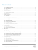
Revision history Revision Date Changes 15.2 August 2014 Table 13: 14-drive RAID policy added. 15.1 May 2014 Minor updates for PS6210. Added information for LLDP. 14.4 February 2014 Section 9.7 Vertical port failover behavior in PS6210 controllers New information in 8.1.2 on how to ensure a secure network environment New information for Controller type 15 in Table 5. 14.
Table of contents 1 2 Purpose ............................................................................................................................................................................................. 7 1.1 Dell statement of support.................................................................................................................................................. 7 1.2 General statement .....................................................................................
8.2 Ethernet switches and infrastructure ........................................................................................................................... 36 8.2.1 Connecting SAN switches in a Layer 2 network........................................................................................................ 37 8.2.2 Sizing inter-switch connections ................................................................................................................................... 40 8.2.
Abstract This configuration guide provides technical guidance for designing and implementing Dell EqualLogic PS Series storage solutions in iSCSI SAN environments.
1 Purpose The goal of this guide is to provide a single reference for technical information, links to other product and technical information, and recommended Dell EqualLogic SAN design methodologies. This document is for informational purposes only and is offered As Is. This document is not intended to be used as: A document for statement of support for any specific configuration Approval for specific configurations or reference architectures 1.
2 Policies and limitations This document is being provided for informational purposes only and may change at any time. This version supersedes and replaces all previous versions. The information included in this document is intended as a guide for planning the configuration of systems for EqualLogic infrastructure and networking environments. It is not intended to be the sole resource for system configurations.
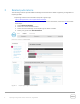
3 Related publications The following locations provide additional background and technical details supporting configuration of EqualLogic SANs. EqualLogic Product Documentation (requires support login) https://eqlsupport.dell.com/support/download.aspx To access the Administration guides and other product documentation, follow this link and follow these steps: 1. Select PS Series Firmware. 2. Select the current firmware version. 3. Select the Download Page of Dell EqualLogic PS Series Firmware. 4.
EqualLogic Compatibility Matrix, including recommended switches and supported iSCSI initiators http://en.community.dell.com/dell-groups/dtcmedia/m/mediagallery/19856862/download.aspx EqualLogic Technical Content http://en.community.dell.com/techcenter/storage/w/wiki/2660.equallogic-technical-content.aspx Rapid EqualLogic Configuration Portal http://en.community.dell.com/techcenter/storage/w/wiki/3615.rapid-equallogic-configurationportal-by-sis.aspx Switch Configuration Guides http://en.community.
4 PS Series storage arrays PS Series storage SANs provide a peer storage architecture comprised of one or more independent arrays. Each array contains its own controllers, cache, storage, and interface ports. Grouped together, they can create one or more single instance storage pools that are based on the IETF iSCSI standard.
Table 2 12 PS4100/PS6100/PS6210 array models Array model Drive type Number of drives PS4100E 3.5” SAS 7.2K RPM 12 PS4100X 2.5” SAS 10K RPM 24 PS4100XV 2.5” SAS 15K RPM 24 PS4100XV 3.5” SAS 15K RPM 12 PS6100E 3.5” SAS 7.2K RPM 24 PS6100X 2.5” SAS 10K RPM 24 PS6100XV 2.5” SAS 15K RPM 24 PS6100XV 3.5” SAS 15K RPM 24 PS6100S SSD 12 or 24 PS6100XS SSD + SAS 10K RPM 7 SSD + 17 SAS PS4110E 3.5” SAS 7.2K RPM 12 PS4110X 2.5” SAS 10K RPM 24 PS4110XV 2.
4.2 PS Series supported configuration limits The Dell EqualLogic PS6xxx Series provides the full range of features and capabilities available with the EqualLogic PS Series storage products. The Dell EqualLogic PS4xxx Series provides a subset of features and capabilities, targeted at remote office and small to medium business storage deployments. The supported configuration limits for a PS Series group are provided in Table 3.
PS4000/PS4100 and PS-M4110 groups onlya All other groupsb Simultaneous management sessions (any combination of GUI, telnet, or scripting sessions) 7 7 Thin provisioningi limits (minimum allocation) 10% of volume size 10% of volume size Administrator accounts per group 100 100 Configuration (a) (b) (c) (d) (e) (f) (g) (h) (i) 14 A group can contain a maximum of two PS4000, PS4100, and/or PS-M4110 arrays.
4.3 Controller types in all models prior to PS4100/PS6100 Array controllers can be identified and differentiated by the controller "type" designation. Each controller type will have a different colored label to help quickly identify the controller type. Table 4 lists each Dell EqualLogic controller along with some characteristics about each.
4.4 Controller types in PS4100/PS6100 models The new controller types available in the PS4100 and PS6100 model arrays became available starting in August 2011. Table 5 lists each Dell EqualLogic controller along with some characteristics.
4.5 Array model PS-M4110 4.5.1 Controller type in PS-M4110 model The PS-M4110 controller is designed based on a modified version of the PS4100 Controller. Host and SAS cards are combined to form a single unit fixed I/O module, connecting to the M1000e chassis infrastructure. Controller Storage blade Type image Type 13 4.5.
S A N S A N LAN LAN SAN Stack SAN Stack LAN/Client Network Figure 3 4.5.3 LAN-to-Agg Uplinks Basic PS-M4110 configuration for data center-in-a-box Networking considerations and guidelines Supported M-Series I/O modules 10G KR is the only supported I/O Module (IOM) Switches: The list of supported switches can be found in the ECM at the following link: http://en.community.dell.com/techcenter/storage/w/wiki/2661.equallogic-compatibility-matrix07262013.
For a more in-depth understanding of PS-M4110 Storage Blade, see the following white papers: Dell EqualLogic PS-M4110 Blade Array Technical Article http://en.community.dell.com/techcenter/storage/w/wiki/4134.dell-equallogic-ps-m4110-bladearray-technical-article.aspx Best Practices for DCB-Enabled Dell M-Series Blade Solution with EqualLogic PS-M4110 http://en.community.dell.com/techcenter/extras/m/white_papers/20422608.
5 Controller firmware 5.1 About member firmware Each control module in a group member must be running the same version of the PS Series firmware. Firmware is stored on a compact flash card or a microSD card on each control module. Dell recommends the following: Always run the latest firmware to take advantage of new features and fixes. All group members must run the same firmware version. If you are adding a new array to a group, update the group to the latest firmware before adding the new member.
Release Notes for any FS Series appliances you are operating Dell EqualLogic PS Series Storage Arrays iSCSI Initiator and Operating System Considerations, available at: http://en.community.dell.com/dellgroups/dtcmedia/m/mediagallery/20371245/download.aspx Updating Firmware for Dell EqualLogic PS Series Storage Arrays, available at: https://eqlsupport.dell.com/support/download.aspx?id=1502 21 EqualLogic Configuration Guide | Version 15.
6 RAID policies Each array in an EqualLogic array group is configured with a single RAID policy. Arrays (or group members) within the same storage pool that have the same RAID policy cooperatively work to host volumes by distributing those volumes over multiple arrays. Two things that are defined by the RAID policy are: RAID level Hot-spare configuration Each array implements a default RAID policy that includes a hot-spare.
7 Capacity planning 7.1 RAID 6 drive layouts and total reported usable storage RAID 6 (striped set with dual distributed parity) combines N disks in an arrangement where each stripe consists of N-2 disks capacity for data blocks and two disks capacity for parity blocks. Each parity block generates parity using a different view of the data blocks depending on the RAID 6 implementation. RAID 6 can tolerate up to two drive failures per RAID stripe set at the same time without data loss.
Table 6 RAID 6 drive layouts and total storage available with hot spares (in GB) Disk drives Hot spare No hot spare 6 5 Data/Parity + 1 Hot-spare 6 Data/Parity 7 6 Data/Parity + 1 Hot-spare 7 Data/Parity 8 7 Data/Parity + 1 Hot-spare 8 Data/Parity 12(f) 11 Data/Parity + 1 Hot-spare 12 Data/Parity 14 13 Data/ Parity + 1 Hot-spare 14 Data/Parity 15 Data/ Parity + 1 Hot-spare 16 Data/Parity 16 8(c) 8+ 15 24(a)(f) 17(e) 7+ 48(a) (a) (b) (c) (d) (e) (f) Data/Parity(d) + 1 Hot-spare 16
Total reported usable storage when using hot spares: PS6210 1 2 25 Drive Qty / Size 146 300 400 600 800 900 1200 2000 3000 4000 24 2478 5079 50841 7035 10179 101821 14076 15278 152801 20336 186142 34550 52204 69857 SED 6210XS only EqualLogic Configuration Guide | Version 15.
7.2 RAID 10 drive layouts and total reported usable storage Using a RAID 10 policy, Table 7 shows the drive layouts that are enforced based on the number of drives in each array/hot spare configuration, and the total usable storage available for each model. RAID 10 (mirrored sets in a striped set) combines two high performance RAID types: RAID 0 and RAID 1. A RAID 10 is created by first building a series of two disk RAID 1 mirrored sets, and then distributing data over those mirrors.
Total reported usable storage when using hot spares: PS6210 1 2 27 Drive Qty / Size 146 300 400 600 800 900 1200 2000 3000 4000 24 1434 2939 29381 4065 5888 58901 8144 8837 88411 11792 N/A2 19999 30218 40443 SED 6210XS only EqualLogic Configuration Guide | Version 15.
7.3 RAID 50 drive layouts and total reported usable storage Table 8 shows the drive layouts that are enforced when using a RAID 50 policy based on the number of drives in each array/hot spare configuration and the total usable storage available for each model. RAID 50 (RAID 5 sets in a striped set) is created by first creating two or more RAID 5 sets and then striping data over those RAID5 sets. RAID 50 implementations can tolerate a single drive failure per RAID5 set.
Total reported usable storage when using hot spares: PS6210 1 2 29 Drive Qty / Size 146 300 400 600 800 900 1200 2000 3000 4000 24 2355 4813 48161 6666 9646 96461 13335 14479 144751 19265 N/A2 32727 49459 66180 SED 6210XS only EqualLogic Configuration Guide | Version 15.
7.4 RAID 5 drive layouts and total reported usable storage RAID 5 (striped disks with distributed parity) will combine N disks in an arrangement where each stripe consists of N–1 disks that contain data blocks plus 1 disk that contains a parity block. For each stripe, the parity block will be placed on a different disk ensuring that the parity blocks are not located on a single disk in the RAID set. RAID 5 implementations can tolerate a single drive failure without data loss.
7.5 Array RAID configurations and associated RAID sets The tables show a logical drive layout when an array is initialized for the first time. The actual physical layout of drives can change and evolve due to maintenance and administrative actions. Spare drives can move as they are utilized to replace failed drives and newly added drives become the spares. It is not possible to determine which physical drives are associated with each RAID set.
Table 13 shows the RAID set relationship for each RAID type in a 14-drive configuration. Table 13 EqualLogic PS Series array RAID types and RAID set relationships Raid policy Spare disks Raid set relationship Best practice RAID 6 1 Spare Disk (11+2), (6+2 HDD, 3+2 SSD)* Yes RAID 10 2 Spare Disks (6+6) Yes RAID 50 2 Spare Disks (5+1, 5+1) For selected configuration RAID 5 1 Spare Disk (12+1) Not for business critical data *Applies to the PS-M4110XS hybrid array configuration.
8 EqualLogic SAN design An EqualLogic iSCSI SAN can be operated in any network that supports the industry standards and IP subnet design guidelines described in this section. Because of this flexibility, there are many network design and configuration choices that can affect SAN performance. The following sections provide details related to network design and configuration to support the use of an EqualLogic SAN.
8.1.2 General requirements and recommendations For EqualLogic PS Series Arrays, the following general SAN design requirements apply: To ensure a secure network environment, Dell strongly recommends the following: - The network environment in which the group resides should be secure from network attacks such as packet sniffing or connection hijacking. This includes network hardware such as switches and routers. Firewalls and network isolation should be employed to protect resources.
At least two iSCSI SAN ports per host (block level iSCSI access) are required for fully redundant SAN connectivity. Host ports can be 1GbE or 10GbE and the the host speed should match the array port speed. Quality of Service (QoS) based on what is traditionally designated as IEEE 802.1p is not currently supported for use with EqualLogic SANs. QoS and Class of Service designations must be disabled.
recommends that you use it only on WANs, where bandwidth is shared with other applications and the PS Series array uses it for time-insensitive replication traffic. Dell recommends against using QoS on the SAN switches. 8.2 Ethernet switches and infrastructure Any switch used in an EqualLogic SAN should meet the requirements listed in this section.
The actual impact on SAN throughput when using jumbo frames will depend on your workload’s I/O characteristics. Support for Rapid Spanning Tree protocol (IEEE 802.1w), or edgeport or Cisco “portfast” functionality if the SAN infrastructure will consist of more than two switches: For SAN infrastructures consisting of more than 2 non-stacking switches, R-STP must be enabled on all ports used for inter-switch trunks.
Figure 4 8.2.1.1 Switch Interconnects Stacking switches Stacking switches provides a simple method for creating a switch interconnection within a Layer 2 network infrastructure. Stacking is typically accomplished using a vendor proprietary, high-bandwidth, low-latency interconnect that allows two or more switches to be connected in such a way that each switch becomes part of a larger, virtual switch.
Table 14 8.2.1.3 Link aggregation types Link aggregation type Notes Static Static link aggregation defines a set of links that provide a point to point connection between two switches. These links may or may not provide failover redundancy or traffic load management. LACP Link Aggregation Control Protocol is based on IEEE 802.3ad or IEEE 802.1AX. LACP is a dynamic LAG technology that automatically adjusts to the appearance or disappearance of links within the defined LACP group.
Figure 5 8.2.2 Using a LAG to interconnect switch stacks Sizing inter-switch connections Use the guidelines in Table 15 as a starting point for estimating inter-switch connection sizes. Table 15 Switch Interconnect Design Guidelines Connection speeds 1GbE switches attached to 1GbE array controllers Interconnection guidelines 1-5 arrays: 1Gb of inter-switch bandwidth per active array controller port (up to the aggregated maximum bandwidth of the inter switch links.
Table 16 Stacking versus LAG Interconnect Primary purpose type Stacking Create a larger, logical switch within an isolated physical location.
9 Building a high-availability SAN Designing a redundant SAN requires the availability of redundant NICs or HBAs on each server. A redundant NIC configuration on the server requires at least two NICs. The information provided here does not address all of the possible variations in a SAN.
The ports must be assigned IP addresses on the same subnet 9.1.2 EqualLogic MPIO General Recommendations Follow this general set of guidelines for configuring MPIO on a host: Configure volume access controls to use standard iSCSI IQN names For a more secure configuration you can use the IQN name plus the CHAP security ID. On each array enable at least two ports for host connectivity.
9.3 Figure 7 Redundant SAN Connection Paths: PS4100 Figure 8 Redundant SAN Connection Paths: PS4110/PS6110 Controller redundancy in all models Each array can be configured with either a single controller, or dual redundant controllers. The single controller configuration will provide the same level of I/O performance as a dual controller configuration. The dual controller configuration provides for redundancy. Dual controllers provide redundancy in the case of a controller failure.
Each of its Ethernet ports are electrically inactive (active lights are off), unless a vertical port failover has occurred. The passive controller cache mirrors the cache of the active controller. 9.4 Basic controller failover behavior in all models To support redundant controller fail over, each Ethernet port on the active controller that is connected to the SAN must have its corresponding port on the passive controller also connected to the same SAN network.
Figure 9 Partially connected controller failover Note how IP addresses are reassigned to their corresponding ports during the failover processes shown in Figure 9 and Figure 10. 46 EqualLogic Configuration Guide | Version 15.
Figure 10 9.4.2 Fully connected controller failover Controller failover behavior for: PS41x0/PS61x0 In the event of a controller failure the following changes occur: The passive controller immediately activates and continues to process all data requests to the array. Vertical port failover ensures that IP addresses assigned to each of the failed controller Ethernet ports apply to the corresponding ports on the second controller. As stated in Section 9.4.
We illustrate controller failover behavior for the PS4100 family controller in Figure 11. Controller failover behavior for the PS6100 (4 port) controller family is identical. Note: To prevent a switch failure from also disabling all paths between a host and its connected volumes, you should make sure that ports from each controller are connected to at least two different switches.
9.5 Vertical port failover behavior in PS4100/PS6100 controllers In PS Series controllers prior to PS4100/6100 families, a link failure or a switch failure was not recognized as a failure mode by the controller. Thus a failure of a link or an entire switch would reduce bandwidth available from the array. Referring to Figure 12 or Figure 13, assume that CM0 is the active controller.
Figure 12 PS4100 vertical port failover Figure 13 PS6100 vertical port failover With PS4100/PS6100 family controllers, vertical port failover can ensure continuous full bandwidth is available from the array even if you have a link or switch failure. This is accomplished by combining corresponding physical ports in each controller (vertical pairs) into a single logical port from the point of view of the active controller.
Figure 14 PS4100 vertical port failover and optimal connection paths IMPORTANT: By alternating switch connection paths between ports in a vertical port pair, port failover allows the array to maintain 100% bandwidth capability in the event of a switch failure. 51 EqualLogic Configuration Guide | Version 15.
Figure 15 9.6 PS6100 vertical port failover process and optimal connection paths Vertical port failover behavior in PS4110/PS6110 controllers In PS Series controllers prior to PS4110/6110 families, a link failure or a switch failure was not recognized as a failure mode by the controller. This caused a failure of a link or an entire switch to reduce bandwidth available from the array. Referring to Figure 12 or Figure 13, assume that CM0 is the active controller.
Figure 16 4110/6110 vertical port failover With the PS4110/PS6110 family of controllers, vertical port failover can ensure continuous full bandwidth is available from the array even if you have a link or switch failure. This is accomplished by combining 10GbE “eth0” ports in each controller into a single logical port from the point of view of the active controller. In a fully redundant SAN configuration, you must configure the connection as shown in Figure 17.
Figure 17 54 4110/6110 Vertical port failover scenario EqualLogic Configuration Guide | Version 15.
9.7 Vertical port failover behavior in PS6210 controllers In PS Series controllers prior to PS4110/6110/6210 families, a link failure or a switch failure was not recognized as a failure mode by the controller. This caused a failure of a link or an entire switch to reduce bandwidth available from the array. Referring to Figure 13, assume that CM0 is the active controller.
Figure 19 56 PS6210 Vertical port failover scenario EqualLogic Configuration Guide | Version 15.
10 Mixed speed environments - Integrating 1GbE and 10GbE SANs With the introduction of 10GbE, there will be situations that require 1Gb arrays and 10Gb arrays coexisting in the same SAN infrastructure. EqualLogic PS Series arrays support operation of 1Gb and 10Gb arrays within the same group.
When connecting 1Gb switches and 10Gb switches together you must always be aware of where Rapid Spanning Tree is going to block links to make sure that 10Gb traffic (i.e. EqualLogic inter-array data flow) never crosses the 1Gb switch. You must configure pools and volumes in a way that minimizes impact to IO performance. - Where possible, always connect 1Gb hosts only to 1Gb arrays and 10Gb hosts only to 10Gb arrays (except when performing migration tasks).
11 Blade server chassis integration Integrating the PowerEdge M1000e Blade Server Solution (or any third party blade chassis implementation) requires additional SAN design considerations. Each M1000e can support up to three separate networking “fabrics” that interconnect ports on each blade server to a pair of blade I/O modules within each chassis fabric through an intervening chassis midplane interface. Each fabric is associated with different interfaces on a given blade server as described in Table 17.
11.1 Designing a SAN using blade chassis I/O modules with arrays There are three categories of SAN designs for M1000e blade chassis integration: 1. Blade IOM switch only ( Direct-Attached ) – Network ports of both the hosts and storage are connected to the M1000e blade IOM switches. No Top of Rack (ToR) switches are required. The switch interconnect can be a stack or a LAG, and no uplink is required. 2.
12 FS Series NAS Configuration In this section we provide detailed connection diagrams demonstrating how to setup fully connected iSCSI SAN and client LAN connection paths for the FS7500 and FS7600/FS7610 appliances. Note: It is recommended to keep the client and SAN side networks physically separate and deploy at least two switches on both sides to provide redundancy in the event of a switch failure. Table 18 lists the basic functional details for each FS Series product. Table 18 12.
Figure 21 shows the client LAN connection paths. Note: While it is possible to operate an FS7500 appliance in a partially cabled configuration, this configuration is not supported by Dell. You should use a fully cabled configuration in a production environment. You will also need to provision the required switch port count on the iSCSI SAN and client LAN sides of the system to support a fully connected configuration.
Figure 22 Connection Paths for FS7500 iSCSI SAN, IPMI and Controller Interconnect The inter-switch connection sizing guidelines provided in Section 8.2.2 also apply to FS7500 SAN design. The FS7500 mirrors the write cache between controller nodes. To accomplish this, all write operations are transmitted across the controller interconnect. Thus, it is very important that you follow connection pattern shown in Figure 22 to ensure corresponding ports are connected to the same switch.
12.2 FS7600/FS7610 connection paths The Dell EqualLogic NAS appliances require the following networks: Client network: Used for client access to the NFS exports and CIFS shares hosted by the NAS cluster. SAN/internal network: Used for internal communication between the controllers and communication between the controllers and the EqualLogic PS Series SAN. The SAN and Internal networks use the same set of switches.
Figure 24 FS7600 network Figure 25 FS7610 network EqualLogic Configuration Guide | Version 15.
Installation/Expansion If installing FS7500/FS76x0 into an existing EqualLogic SAN, verify the existing LAN and SAN networks meet the minimum requirements. All NAS appliances in a NAS cluster must be of the same speed. Appliances with different connectivity cannot be mixed in a NAS cluster. - An FS7500 cluster can be expanded by using another FS7500 or an FS7600 but NOT an FS7610. Do not block IPv6 traffic on the SAN internal switches when utilizing FS Appliances.
13 Data Center Bridging (DCB) The enhancement to the Ethernet Specifications (IEEE 802.3 specifications) called Data Center Bridging (DCB) enables bandwidth allocation and lossless behavior for storage traffic when the same physical network infrastructure is shared between storage and other traffic. The network is the fundamental resource that connects the assorted devices together to form the datacenter Ethernet infrastructure.
13.1 DCB Overview DCB is a collection of Standards designed to improve networking and management in the Data Center that enables iSCSI SANs or FCoE SANs or both to converge with regular server LAN traffic on the same physical infrastructure. DCB aims to increase operational efficiency, constrain costs, and ease network management.
PFC - Requires enabling PFC (no drop or lossless behavior) for iSCSI priority Switches: Configure dedicated TC/PG for iSCSI priority with allocated bandwidth and PFC enabled for iSCSI priority Server NICs/CNAs: Adhere to TC/PG mapping for iSCSI priority and PFC for iSCSI priority (learned from the switch) Designing a converged network deployment with components that have no DCB support or partial DCB support is not recommended for end-to-end converged I/O.
All devices in the iSCSI data path must have the same VLAN ID configured on the respective ports participating in the iSCSI network to ensure proper functioning. These devices include the server iSCSI NIC/CNA ports, EqualLogic arrays, and all switches on the iSCSI SAN. Note: The VLAN ID for iSCSI can be set in the EqualLogic Group Manager interface or the storage array CLI.
A Network ports and protocols PS Series groups use a number of TCP and UDP protocols for group management, I/O operations, and internal communication. If you have switches or routers set to block these protocols, you may need to unblock them to allow management or I/O operations to work correctly. The required and optional protocols are listed in the following sections. A.1 Required ports and protocols Table 19 lists the ports and protocols required for operating an EqualLogic iSCSI SAN.
Table 20 Type Optional ports and protocols Port Protocol Access CLI Management TCP 23 Telnet To group IP address TCP 22 SSH To group IP address Web Based Management TCP 80 HTTP To group IP address TCP 3002 GUI communication To group IP address TCP 3003 GUI communication (encrypted) To group IP address 161 SNMP To and from group IP address 514 Syslog From group IP address SNMP UDP Syslog UDP EqualLogic Diagnostics TCP 21 FTP Software update and diagnostic procedures; to all
B Upgrade paths for EqualLogic PS Series arrays Table 21 73 EqualLogic upgrade paths End of sales life arrays: Latest available conversion model 1Gb to 10Gb conversion availability Drive upgrades availability PS-50 thru PS3000 None None None PS4000 Yes, PS6000 Yes, PS6010 Yes PS5000 Yes, PS6000 Yes, PS6010 Yes PS6000 None Yes, PS6010 Yes PS5500 Yes, PS6500 Yes, PS6510 Yes PS6010 None N/A Yes Currently shipping arrays: Latest available conversion model 1Gb to 10Gb conversion