
Technical information


61 EqualLogic Configuration Guide | Version 15.2 | August 2014
12 FS Series NAS Configuration
In this section we provide detailed connection diagrams demonstrating how to setup fully connected
iSCSI SAN and client LAN connection paths for the FS7500 and FS7600/FS7610 appliances.
Note: It is recommended to keep the client and SAN side networks physically separate and deploy at
least two switches on both sides to provide redundancy in the event of a switch failure.
Table 18 lists the basic functional details for each FS Series product.
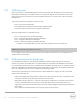
Table 18 FS Series Models
FS Series model
System components
I/O connections
FS7500
2 x 1U NAS appliance; dual
active-active controller
configuration
1 x 1U Battery backup power
supply unit (BPS)
Client LAN: 8x1GbE per
appliance (4 per controller
node)
iSCSI SAN: 8x1GbE per system
(4 per controller node)
Controller Interconnect:
8x1GbE per system (4 per
controller node)
FS7600
2U NAS appliance with two
active/active NAS controllers.
Client LAN: 8x1GbE per
appliance (4 per controller
node)
iSCSI SAN: 8x1GbE per system
(4 per controller node)
FS7610
2U NAS appliance with two
active/active NAS controllers.
Client LAN: 4x10GbE per
appliance (2 per controller
node)
iSCSI SAN: 4x10GbE per system
(2 per controller node)
12.1 FS7500 connection paths
The FS7500 appliance is comprised of two peer system controller nodes. In the required fully cabled
configuration, each controller node requires thirteen separate Ethernet cable connections. Thus a single
FS7500 appliance comprised of two controller nodes requires a total of 26 Ethernet connections (four
connecting to the client LAN switches and nine connecting to the iSCSI SAN fabric switches.)