Please read this manual carefully before installation and keep it for future reference. Installation & Owner’s Manual DIY E Star™ Series ® Due to updates and constantly improving performance, the information and instructions within this manual are subject to change without notice. Please visit www.mrcool.com/documentation to ensure you have the latest version of this manual.
Contents ! Safety Precautions Warnings .................................................................................................................................. Cautions ................................................................................................................................... 1 Parts Overview 2 Operating Instructions 3 Care and Maintenance Parts Diagram ..................................................................................................................
Contents 4 Indoor Unit Installation ...........15 1. Selecting an installation location .........15 4. Prepare refrigerant piping ....................18 5. Mount indoor unit ..................................18 5 Outdoor Unit Installation ...... 19 1. Selecting an installation location ......19 2. Install drain joint .................................20 .21 Refrigerant Piping Connections......................23 1. Prepare Exterior Wall Hole ............................................. 23 2.
Safety Precautions Safety Precautions Read Before Using ! Incorrect usage may cause serious damage or injury. The symbols below are used throughout this manual to indicate instructions that should . be followed closely or actions that should be avoided to prevent death, injury, and/or property damage.
Safety Precautions 7. 8. All wiring must be properly arranged to ensure that the control board cover can close properly. If the control board cover is not closed properly, it can lead to corrosion, which can cause the connection points on the terminal to overheat, which car result in fire and/or electrical shock. 9.
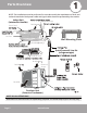
Parts Overview Safety Precautions 1 NOTE: The installation must be performed in accordance with the requirement of local and national standards. Both power cable and signal cable should be protected by the conduit.
Overview - Display 2 ° 3 ECO 4 Fig. 1.2 Display (on front panel of indoor unit) 1. Digital Display: Displays the Temperature Setting when the air conditioner is operational. Displays the Room Temperature when in FAN mode. Displays the self-diagnostic codes. Displays “ ON” for three seconds when the Timer is ON and/or Fresh, Swing, Turbo, or Silence feature is activated. Displays “ OF” for three seconds when the Timer is switched OFF .
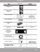
Accessories The air conditioning system includes the following accessories. Use all of the installation parts and accessories to install the air conditioner. Improper installation may LOOKS LIKE... 1 Mounting plate 5 Mounting plate screw 5 Remote control 1 Fixing screw for remote 2 ST2.9 x 10 Optional Parts 1 Dry battery AAA.
Accessories LOOKS LIKE... Please read this manual carefully before installation and keep it for future reference. Installation & Owner’s Manual Owner’s Manual 1 E-Star™ DIY Series For more details visit www.MrCool.com Please read this manual carefully before installation and keep it for future reference. Remote Control Manual Remote Control User Manual 1 For more details visit www.MrCool.
Safety Precautions Operating Instructions Cooling Operation Room Temperature Outdoor Temperature 2 Heating Operation Drying Operation 32°F~86°F (0°C~30°C) 63°F~90°F °C~32°C) 32°F~ F (0°C~50°C) 5°F~75°F C~24°C) 50°F~90°F °C) F 32° F~ (0°C~50°C) (For the models with low ambient cooling system) NOTE: 1. 2. Manual Operation Units are equipped with a button to run emergency operation mode. This button is used for manual operation in case the remote control fails, or maintenance is necessary.
Operating Instructions Adjust Vertical Airflow (Up/Down) using Vertical Louver (Fig 2.2): This function is performed by using the remote control, while the unit is operating. The Vertical louver can move in small increments for each press, or continuously swing up and down automatically. Please refer to the “Remote Control User Manual” for further details.
Operating Instructions Basic Operation Modes: SLEEP operation Auto Operation: 8 hours timer OFF Set Temperature hour SLEEP Operation: hour SLEEP Operation While Cooling SLEEP operation hours before SLEEP DRYING Operation: 8 hours timer OFF LOW . Set Temperature HEATING Operation: hour hour SLEEP Operation While Heating supplement heating with other appliances.
Operating Instructions Special Functions Refrigerant Leakage Detection (optional): Louver Angle Memory Function (optional): Anti-Mildew Function (optional): When the unit is turned off, in COOL, DRY, or AUTO (cool) modes, it will continue to run for about 10 minutes with low fan airflow. This is to aid in drying any condensation that has formed inside the unit to prevent mildew growth. Do not restart the air conditioner until the unit is completely off.
Operating Instructions Care and Maintenance 3 CAUTION Power supply must be disconnected before attempting any kind of cleaning or service. Before performing maintenance, turn the power off to the unit and then disconnect the power to the circuit at the breaker. Failure to do this could cause electrical shock. DO NOT use a chemically treated cloth or duster to clean the unit. DO NOT use benzene, thinner, polishing powder, or similar solvents for cleaning.
Care and Maintenance 3 3. 4. 5. . 4 7. lowering the bottom into place. 8. Removal Install Preparation for Extended non-Operation: 5 1. 2. 3. Turn off the unit. Then, turn off the power to the circuit at the breaker. The unit should be the only appliance on this circuit. 4. 5. The outdoor unit also requires periodic maintenance. However, it is highly recommended you contact a qualified service professional to perform this. Please do not attempt to do this on your own.
Installation Summary - Indoor Unit Indoor Unit Installation DO NOT install unit in the following locations: Installation Instructions – Indoor Unit Near any source of heat, steam, or combustible gas PRIOR TO INSTALLATION: Before installing the indoor unit, refer to the label on the product box to make sure that the model numbers of the indoor unit and the outdoor unit match. Step 1: Selecting an installation location choose an appropriate location.
Indoor Unit Installation Refer to Fig. 4.2 below to ensure proper distance from walls, ceiling, and floor when mounting unit: Minimum Ceiling Clearance 5.9 in (15 cm) Minimum Side Clearance 4.75 in (12 cm) Minimum Side Clearance 4.75 in (12 cm) *For Ceilings GREATER than 9 ft., recommended distance from floor 90.55 in (230 cm) *For Ceilings LESS than 9 ft., recommended distance from floor 78.55 in (200 cm) Fig. 4.
Indoor Unit Installation MOUNTING PLATE DIMENSIONS NOTE REGARDING WALL STUDS on studs. In order to ensure that you have ample room to mount the indoor unit, the diagrams to the right 9.15 in (232 mm) 5.05 in (128 mm) 1.7 in (43 mm) 7.55 in (192 mm) Outline of indoor unit when mounted to plate 1.7 in (43 mm) Correct orientation of Mounting Plate 16.8 in (426 mm) 1.7 in (43 mm) • Do not attempt a left rear wall hole. marked “US” on the metal bracket. 11.
Indoor Unit Installation Step 4: Prepare indoor unit refrigerant piping Step 5: Mount the Indoor Unit The piping of the indoor unit is attached to the back of the unit towards the bottom. It will be covered with insulation, and there will also be a drain pipe with these. This piping will need to be bent and prepared before it can be fed through the wall hole. In the following steps the indoor unit will now be mounted to the wall bracket and the piping and wires will be fed through the wall hole. 1.
Indoor Unit Installation Outdoor Unit Installation Minimum clearance in fr 7o 9in nt (2 of0u 0n cm it:) 7in 9 in fro(2 nt00cm) Installation Instructions – Outdoor Unit Step 1: Selecting an installation location choose an appropriate location. Use the following guidelines to help you select an appropriate location.
Outdoor Unit Installation If the drain joint comes with a rubber seal SPECIAL CONSIDERATIONS FOR EXTREME WEATHER Fig. 1. angle to the direction of the wind. If needed, build a barrier in front of the unit to protect it from extremely heavy winds. Ensure the wind barrier does not block Fig. 5.2 and Fig. 5.3 below. 2. 3. the unit. facing the front of the unit. 4. Strong wind If the drain joint does not come with a rubber seal 1. Strong wind Fig. 5.2 2.
Outdoor Unit Installation TOP VIEW FRONT VIEW A Air Inlet D H Air Inlet B Air Outlet W Fig. 5.5 UNIT MOUNTING DIMENSIONS sizes and the distance between their mounting feet. Prepare the installation base of the unit according to the dimensions in the table below, using the illustrations of the unit above (Fig 5.5) as a reference/guide to correspond with the table. Mounting Dimensions: Inches (Millimeters) Outdoor Unit Dimensions: Inches (Millimeters) Width (A) Depth (B) 20.24 in (514 mm) 13.
Outdoor Unit Installation If you are installing the unit on a wall-mounted bracket, follow these steps: Before installing a wall-mounted unit, make sure that the wall is made of solid brick, concrete, or a similarly strong material. The wall must be able to support at least 4 times the weight of the unit. 1. 2. 3. 4. 5. the 7. 8. MOUNTED UNIT ATION OF WALL- If allowed, you can install the wall-mounted unit with rubber gaskets to reduce vibration and noise. mrcool.
Refrigerant Piping Connection Step 1: Prepare exterior wall hole Before the refrigerant piping can be installed and connected to the indoor and outdoor units, some additional steps are required to prepare the exterior. 1. Install finishing ring/cap to exterior portion of the wall hole. 2. Place your hand on the underside of the piping coming through the exterior wall hole (from indoor unit), close to the wall.
Refrigerant Piping Connection Step 3: Connect Line Set to Indoor Unit 3.1 Tools needed NOTE: Depending on the capacity rating of your unit, (12K, 18K, 24K, 36K) the wrench sizes needed will vary, refer to the table below (the unit uses metric sizes, the standard sizes listed are approximations). Based on the availability of wrenches in some of the sizes needed, the recommended method is to use crescent (adjustable-type) wrenches that can be adjusted to fit the size each step requires. .
Refrigerant Piping Connection TORQUE REQUIREMENTS 1. 2. 3. NOTE: Torque ratings in the table below are to be used if you have access to an HVAC torque wrench. These are available for purchase from online retailers. However, it is possible to complete installation of refrigerant line sets with conventional open-ended/crescent wrenches. It is imperative, however, that you not overtighten the connector, and that once the lines have been fully connected, you follow the steps to check for leaks.
Refrigerant Piping Connection CAUTION Step 4: Connect Line Set to the Outdoor Unit 1. IMPORTANT: Before you continue, it is essential that you read the following instructions carefully. shown in the illustration. 4. Using the first image below as a guide, starting with the bottom screw connector, you will now tighten the line set to the outdoor unit.
Refrigerant Piping Connection TORQUE REQUIREMENTS Excessive force can break the nut or damage the refrigerant piping. You must not exceed torque requirements shown in the table below. 2. 3. versus a HVAC torque wrench) and that a socket style wrench cannot be used here. NOTE: Torque ratings in the table below are to be used if you have access to an HVAC torque wrench. These are available for purchase from online retailers.
Refrigerant Piping Connection Step 5: Opening the refrigerant valves of the outdoor unit 2. Using the images below as a guide, repeat the same 1. Using the images below as a guide, remove the cover on the top valve, using a 19 mm open-ended wrench or a crescent (adjustable-type) wrench. Then, insert a 5 mm Allen key and open the valve by turning it counter-clockwise as far as it will go. DO NOT force it. The valve is now open.
Refrigerant Piping Connection Step 6: Wrap piping connections In this step you will wrap and insulate the exposed line connections coming from the indoor air handler. IMPORTANT Refrigerant piping Do not complete these steps until all of the refrigerant piping connections have been checked for leaks. 1. Wrap the connectors at the indoor air handler tightly with the supplied sound deadening pads. 2.
Refrigerant Piping Connection Step 7: Connect Drain Pipe Make sure there are NO kinks or dents in the hose to ensure proper drainage. In this step you will connect the drain hose extension to the drain hose exiting from the indoor unit that is within the piping bundle you wrapped in the previous steps. 1. Securely connect the drain hose extension to the drain piping from the indoor unit. Fig. 4.5a NOT CORRECT KINKS in the drain hose will create water traps. 2. Using example Fig. 4.
Refrigerant Piping Connection Wrapped piping with U.V. Tape Quick Connect® connections Signal Cable (inside conduit) Drainage Pipe Refrigerant Piping Sound Deadening Pads to wrap connections once connected and checked for leaks. Coiled & Wrapped excess refrigerant line Outdoor Unit (Exterior / Condenser) BEFORE PERFORMING ELECTRICAL WORK, READ THESE REGULATIONS 1. All wiring must comply with local and national electrical codes. 2.
7 Electrical Connections Connect signal and power cables A comprehensive wiring diagram is printed on the inside of the wiring cover. E G L K N general conventions. below. WIRE CONNECTING DIAGRAM (12K Unit Only) 1 2 3 L1L2 Fig. 7.
Electrical Connections 1. SELECT THE CORRECT CABLE • See table below for gauge requirements Minimum Wire Gauge for Power Cables Model Series Appliance Amps (A) Cover Outdoor Unit Wiring Diagram is located on wire cover on AWG 20 20 24K 30 36K 40 Fig. 7.2 8 NOTE ABOUT FUSE SPECIFICATIONS ALL WIRING MUST BE INSTALLED STRICTLY IN ACCORDANCE WITH THE WIRING DIAGRAM LOCATED AS SHOWN IN FIG 7.2. designed with a fuse to provide overcurrent printed on the circuit board. 2. EXAMPLE 3.
Refrigerant Piping Connection 88 WARNING – RISK OF ELECTRIC SHOCK Manual. BEFORE TEST RUN ALL WIRING MUST BE INSTALLED BY A LICENSED ELECTRICIAN AND COMPLY WITH LOCAL, STATE, AND NATIONAL ELECTRICAL CODES. There are two different methods to check for gaseous leaks. NOTE: DURING TEST RUN Soap and Water Method Using a soft brush or spray bottle, apply a soapy water solution to all of the pipe connection points of the indoor and outdoor units, watching to see if any bubbles form.
Refrigerant Piping Connection Test Run 9 Before Test Run PASS/FAIL Only perform test run after you have completed the following steps: No electrical leakage – • the electrical system is safe and operating properly • Unit is properly grounded – not leaking properly covered • pressure) valves are fully open Indoor and outdoor units are solidly installed Wall Penetration Sleeve is packed airtight Test Run Instructions You should perform the 30 minutes.
Test Run DOUBLE-CHECK PIPE CONNECTIONS During operation, the pressure of the refrigerant circuit/piping will increase. This may reveal leaks that were not present during your initial leak check. Take time during the Test section for instructions. 5. a. Manual Control Button operating temperature. b. Fig. 9.1 IF AMBIENT TEMPERATURE IS BELOW If the ambient temperature is below 63°F (17°C), the remote controller cannot be used to turn on the COOL function.
10 The following events may occur during normal operation, and may not indicate a malfunction. Symptom Cause Operation is delayed after restart The protection circuit will prevent the compressor from operating for roughly 3 minutes, after a sudden ON-OFF operation of the power supply, in order to prevent a blowout of the fuse.
Symptom Diagnostic -- Is there a power failure? Unit will not operate -- Is the timer operating? batteries used in the remote controller exhausted? batteries used in the remote controller installed properly? temperature and mode settings correct? Poor cooling or windows or doors left opened? -- Is direct or strong sunlight shining into the room in cooling operation? re other heat generating devices (such as a computers operating), or too many people in the room in cooling operation? become lower.
Indoor Unit Error Display O(light) Operation LED X(off) (flash) Timer LED Display 1 time X E0 Indoor unit EEPROM parameter error 2 times X E1 Indoor / outdoor units communication error ** 3 times X E2 Zero-crossing signal detection error 4 times X E3/E88 5 times X E4 Indoor room temperature sensor T1 open circuit or short circuit 6 times X E5 Evaporator coil temperature sensor T2 open circuit or short circuit 7 times X EC Refrigerant leakage detection 2 times O F1 Outdoor
DIY E Star Series ® Consult with the sales agency or manufacturer for details.