MR. HEATER HEATSTAR READ INSTRUCTIONS CAREFULLY: Read and follow all instructions. Place instructions in a safe place for future reference. Do not allow anyone who has not read these instructions to assemble, light, adjust or operate the heater.
WARNING: WARNING: YOUR SAFETY IS IMPORTANT TO YOU AND TO OTHERS, SO PLEASE READ THESE INSTRUCTIONS BEFORE YOU OPERATE THIS HEATER. FIRE, BURN, INHALATION, AND EXPLOSION HAZARD. KEEP SOLID COMBUSTIBLES, SUCH AS BUILDING MATERIALS, PAPER OR CARDBOARD, A SAFE DISTANCE AWAY FROM THE HEATER AS RECOMMENDED BY THE INSTRUCTIONS NEVER USE THE HEATER IN SPACES WHICH DO OR MAY CONTAIN VOLATILE OR AIRBORNE COMBUSTIBLES, OR PRODUCTS SUCH AS GASOLINE, SOLVENTS, PAINT THINNER, DUST PARTICLES OR UNKNOWN CHEMICALS.
BEFORE YOU BEGIN Available Accessories Read this manual carefully before installing or servicing this equipment. Improper installation, servicing or maintenance will cause death, injury or property damage. Check the minimum required safe distances from combustibles given on the outside of each burner to make sure that the product is suitable for your application. The minimum required safe distances from combustibles is also found on page 9 of this manual.
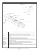
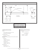
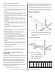
About The Heater Intake Vent Exhaust Vent 1/2" NPT Power Cord Burner Box - Rear View Front Fixed Hanger Reflector Heat Exchanger Rear Movable Hanger Control Side Access Burner Box Contains the electrical components (i.e. blower motor, power transformer, etc.) and gas distribution components (i.e. gas valve, etc.) that make the heater work. There are no owner serviceable items contained in this box. Front Fixed Hanger Provides rigid support and mounting surface for the reflector.
Technical Specifications: Length 111/2" 1" Max. Burner Box 131/2 " Reflector Suspension Points Heat Exchanger - Side View - End View - 9" Leading Particulars Model No. BTU/hr Weight Length MHT- 45 45,000 96 lbs. 10’ HST- 45 45,000 96 lbs. 10’ VENTING SPECIFICATIONS HEATER SPECIFICATIONS Electrical Vent/Flue Length – 25 feet (Maximum) Rating: 120VAC, 60Hz, single phase, 1 amp 5 feet (Minimum) Connection: 3 pin molded plug Flue Pipe – 3.
Where can the heater be installed? Section 2 PLANNING The MHT/HST tube heater is intended for installation in the following areas: General • Residential applications, such as: This section provides the following information: — garages • Defines the gas, electric and venting requirements for the MHT /HST tube heater. — greenhouses • Specifies the national standards and applicable codes that apply to the gas, electric and venting requirements.
Electrical Service Requirements: System Requirements ATTENTION Risque de monoxyde de carbone L echappement du radiateur doit s’effectuer a l’exterieur. Utillisez le materiel fourni. Le non-respect de ces consignes peuvent avoir resultat la mort ou la blessures. The MHT/HST tube heater requires a grounded three-prong electrical outlet to be installed within 18 inches of the rear surface of the heater’s burner box.
Section 3 INSTALLATION Installation Materials Materials required for the installation of the MHT / HST tube heater include at a minimum the following: WARNING Several steps are involved in the installation of the heater. DO NOT attempt to operate the heater until ALL steps of the installation have been accomplished. Failure to follow this warning can cause death, injury or property damage.
General Guidelines (Residential) It is important to keep the minimum required safe distances from combustibles at all times to avoid death, personal injury or property damage. Clearances from vehicles parked beneath heaters must be maintained. Signs should be posted to identify any possible violation of the clearance distances form the heater in the vehicle areas. Maximum allowable stacking height in storage areas should be identified with signs or appropriate markings.
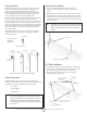
Hang the Heater Horizontal Installation Residential garages come in a variety of sizes, shapes, styles and methods of construction. Because of all these variables, it is not possible to include mounting hardware with the MHT / HST heater. Although wooden rafters and joists are the most common overhead structural members in residential garage applications, other structural configurations are also illustrated below. 1.
MHT / HST HEATER ASSEMBLY INSTRUCTIONS 1. Place gaskets from Gasket kit (02885) on each side of the burner box. Use the four mounting studs around each of the three-inch holes for location. 2. Slide the tube flanges over the studs as was done in the prior step with the gaskets. The tube ends extend through the flanges to help with alignment. 3. Using the four long and four short nuts from the bolt kit (02876) secure the tube set to the burner box.
Typical Installation Section 4 VENTING The Illustration below shows a typical installation of the MHT / HST tube heater. The installation drawing shown has a straight horizontal venting arrangement and specifies the minimum space required for maintenance, as well as the allowable range of distances between the two suspension points. This appliance is certified under the ANS/CSA Standard for Vented Gas-Fired Space Heating Appliances.
The seams along the length of the piping and the joints between sections of piping should be sealed to prevent a potential leakage of flue gas into building. Use 100% RTV Silicone Rubber Adhesive sealant suitable for 500°F. BASIC FLUE VENTING (Residential Only) • Venting must be in compliance with the latest edition of the National Fuel Gas Code (ANSI. Z223.1 latest edition: or the authority having jurisdiction.
MINIMUM HEIGHT FROM ROOF NOTE : To minimize problems associated with condensation in long runs, vent pipe can be insulated. TO LOWEST DISCHARGE OPENING Roof Pitch Flat H (Min) to 6/12 3. The horizontal venting system approved with this heater consists of the Side Wall Vent Kit (02840) shown are page 3. 1.0 Feet Over 6/12 to 8/12 1.5 Feet Over 8/12 to 10/12 2.5 Feet Over 10/12 to 12/12 4.0 Feet 4. Limit the quantity of 90° elbows to two.
a) Be sure that method selected for venting heater complies with all codes as required for each particular location. Single Wall Single wall vent run Single wall terminal end b) Exhaust end of heater will accept a three (3") inch flue pipe using the flue pipe adapter. c) Heater may be vented to the outdoors either vertically or horizontally. d) If heater is to be vented horizontally: 1) Vent must exit building not less than seven (7') feet above grade when located adjacent to public walkways.
VERTICAL THROUGH THE ROOF Vertical Venting Vent Cap (Leslie VersaCap) 3" Dia. Single-Wall Pipe 3' Min. 6" Min. Flashing 3" Starting Collar ¼” per ft. downwards Air For Combustion (Residential) If indoor combustion air is to be supplied for a tightly enclosed area, one square inch of free area opening shall be provided below the heater for each 1,000 Btu/hr of heater input.
Low Voltage Thermostat Wiring Diagram Heaters are normally controlled by thermostat. The recommended 24V thermostat, connects to the unit as shown in the diagram below. Heater CAUTION Label all wires prior to disconnection when servicing controls. wiring errors can cause improper and dangerous operation. Verify proper operation after servicing.
when such use is in compliance with local codes. All pipe, tube and fittings should be new and free from defects. Carefully ream the pipe and tube ends to remove obstructions and burrs. Supplied by others 3. Use LP-resistant joint compound on all threads. 4. Check the pipe and tube connections for leaks before placing heating equipment into service. When checking for gas leaks, use a soap and water solution; never use an open flame.
Operation of the Heater For best performance, the following maintenance procedures should be performed by a qualified service agency before each heating season: CHILDERN AND ADULTS SHOULD BE ALERTED TO THE HAZARDS OF HIGH SURFACE TEMPERATURES AND SHOULD STAY AWAY TO AVOID BURNS OR CLOTHING IGNITION. 1. A qualified service agency should be contacted for service other than routine maintenance. YOUNG CHILDERN SHOULD BE CAREFULLY SUPERVISED WHEN THEY ARE IN THE SAME SPACE AS THE HEATER.
Section 7 TROUBLESHOOTING General This troubleshooting guide has been designed to assist you in locating and correcting minor problems that may occur with the MHT / HST tube heater. BLOWER DOES NOT COME ON Possible Cause Try This…. Power cord is not plugged in. Plug power cord into a grounded three prong Outlet. Thermostat setting is too low. Increase thermostat temperature setting. DSI module needs to be reset. Unplug heater power cord from the electrical Outlet: wait for a minimum of five seconds.
BURNER DOES NOT LIGHT Possible Cause Try This…. Air in the gas line. Purge gas lines. Improper gas inlet pressure. Check gas inlet pressure at the 1/8” NPT plugged tap. Gas inlet pressure should be as follows: Natural Gas: 5.0”w.c. min.; 10.5” max. LP Gas: 11”w.c. min.; 13.0” max. If gas inlet pressure does not meet inlet pressure requirements contact the gas company. Check for 24V across valve terminals. Gas valve does not open. Check Shutoff On Valve.
Section 8 ILLUSTRATED PARTS Illustrated Parts This section provides the part numbers and pictorials for components of the MHT / HST tube heater. Callout letters on the illustrations are keyed to the associated parts list.
MHT / HST 45 Tube Heater A E G D B F C REPLACEMENT PARTS LIST FOR HEATER MODEL MHT / HST TUBE HEATER REF.
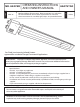
MR. HEATER HEATSTAR MODEL MODEL MHT 45 OPERATING INSTRUCTIONS AND OWNER’S MANUAL HST 45 WARNING: USE ONLY MANUFACTURER’S REPLACEMENT PARTS. USE OF ANY OTHER PARTS COULD CAUSE INJURY OR DEATH. REPLACEMENT PARTS ARE ONLY AVAILABLE DIRECT FROM THE FACTORY AND MUST BE INSTALLED BY A QUALIFIED SERVICE AGENCY. FOR INFORMATION REGARDING SERVICE OR PARTS: Contact your local heating service technician or dealer. FOR ADDITIONAL INFORMATION: Please call Toll-Free 800-251-0001 -WWW.mrheater.com or WWW.enerco.