
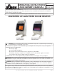
Use and Care Manual

8
Installation Instructions and Owner’s Manual
Unvented Natural Gas Fired Room Heater
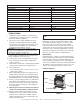
Figure 10
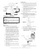
2. Mark screws locations on wall.
3. Remove heater from mounting bracket.
4. If installing bottom mounting screw into hollow
or solid wall, install wall anchors. Follow steps 1
through 4 under Attaching to Wall using Anchor.
If installing bottom mounting screw into wall
stud, drill holes at marked locations using 9/64”
drill bit.
5. Re-place heater onto mounting bracket.
6. Place spacers between bottom mounting holes
and wall anchor or drilled hole.
7. Hold spacer in place with one hand. With the
other hand, insert mounting screw through
bottom mounting hole and spacer. Place tip of
screw in opening of wall anchor or drilled hole.
8. Tighten both screws until heater is fi rmly
secured to wall. Do not over tighten.
Note: Do not re-place front panel at this time. Re-
place front panel after making gas connections and
checking for leaks.
FLOOR MOUNTING AWAY FROM WALL:
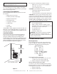
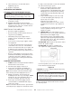
Installing Support Feet (see fi gure 11)
1. Lay heater onto table on its back with bottom
edge overhanging table edge.
2. Securely attach feet to bottom of heater using
2 – self-tapping screws each.
Figure 11
Note: Feet should have long end going out the
front of heater, and the edge coinciding with side of
heater. If feet overhang side of the heater, switch
leg location.
3. Place heater on non-combustible surface (see
Locating Heater, page 6) before proceeding
with gas connection. If this will be a permanent
location, heater may be locked into position
using anchoring holes in mounting feet.
Note: Use of fl oor mounting feet will require
you to use a 3/8 NPT street elbow to make gas
connection.
CONNECTING TO GAS SUPPLY
WARNING: A qualifi ed service person must con-
nect heater to gas supply. Follow all local codes.
WARNING: This appliance requires a 3/8” NPT
(National Pipe Thread) inlet connection to the
pressure regulator. Use of fl oor mounting feet will
require you to use a 3/8 NPT street elbow to make
gas connection.
CAUTION: Never connect heater to private (non-utility)
gas well. This gas is commonly known as well-head gas.
IMPORTANT: Check your gas line pressure before
connecting heater to gas line. Gas line pressure
must be no greater than 14 inches of water. If gas line
pressure is higher, heater regulator damage could
occur.
CAUTION: Use only new black iron or steel pipe.
Internally-tinned copper tubing may be used in certain
areas. Check your local codes. Use pipe of larger
enough diameter to allow proper gas volume to heater.
If pipe is too small, undue loss of pressure will occur.
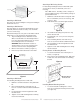
Installation must include an equipment shutoff valve,
union and plugged 1/8” NPT tap. Locate NPT tap within
reach of test gauge hookup. NPT tap must be upstream
from heater (see fi gure 12).
*A CSA/AGA certifi ed equipment shutoff valve with
1/8” NPT tap is an acceptable alternative to test gauge
connection. Purchase the CSA/AGA certifi ed equipment
shutoff valve from your dealer.
IMPORTANT: Install an equipment shutoff valve in an
accessible location. The equipment shutoff valve is for
turning on or shutting off the gas to the appliance.
Apply pipe joint sealant lightly to male threads. This will
prevent excess sealant from going into pipe. Excess
sealant in pipe could result in clogged heater fuel train.
CAUTION: Use pipe joint sealant that is resistant to
natural gas.
Install sediment trap in supply line as shown in fi gure
12. Locate sediment trap where it is within reach
for cleaning. A sediment trap traps moisture and
contaminants. This keeps them from going into heater.
If sediment trap is not installed or is installed improperly,
heater may not run correctly.
IMPORTANT: Hold pressure regulator with wrench
when connecting it to gas piping and/or fi ttings.
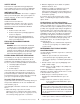
Screw
hole
Screw
hole