
Use and Care Manual

9
Installation Instructions and Owner’s Manual
Unvented Natural Gas Fired Room Heater
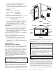
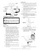
Figure 12
CHECKING GAS CONNECTIONS
WARNING: Test all gas piping and connections for
leaks after installing or servicing. Correct all leaks
at once.
WARNING: Never use an open fl ame to check for
a gas leak. Apply a mixture of liquid soap and water
to all joints. Bubbles forming show a leak. Correct
all leaks at once.
PRESSURE TESTING GAS SUPPLY PIPING
SYSTEM
High Pressure
Test pressure in Excess of ½ psig (3.5kPa)
1. The appliance and its appliance main gas valve
must be disconnected from the gas supply
piping system during any pressure testing of
that system at test pressures in excess of ½
psi (3.5 kPa). The appliance must be isolated
from the gas supply piping system by closing
its equipment shutoff valve during any pressure
testing of the gas supply piping system at test
pressures equal to or less than ½ psi (3.5 kPa).
2. Cap off open end of gas pipe where equipment
shutoff valve was connected.
3. Pressurize supply piping system by either using
compressed air or opening main gas valve on
or near gas meter.
4. Check all connections and joints in gas supply
piping system. Apply mixture of liquid soap and
water to gas joints. Bubbles forming show a leak.
5. Correct all leaks at once.
6. Depressurize and relieve pressure in supply
piping system.
7. Reconnect heater and equipment shutoff valve
to gas supply.
8. Reconnected fi ttings must be checked for leaks
in next section.
Low Pressure
Test Pressure Equal To or Less Than ½ psig (3.5 kPa)
1. Close equipment shutoff valve (see fi gure 13).
2. Pressurize supply piping system by either using
compressed air or opening main gas valve on
or near gas meter.
3. Check all joints from the gas meter to
equipment shutoff valve (see fi gure 14). Apply
mixture of liquid soap and water to gas joints.
Bubbles forming show a leak.
4. Correct all leaks at once.
5. Depressurize and relieve pressure from supply
piping system.
Pressure Testing Heater Gas Connections:
1. Make sure that the heater supply piping system
is connected and has been leak tested as
described above.
2. Make sure control knob of heater is in OFF
position.
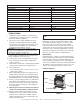
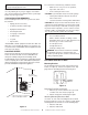
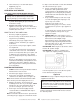
Figure 13
3. Open equipment shutoff valve (see fi gure 13).
4. Open natural gas supply valve.
5. Check all joints from equipment shutoff valve
to control valve (see fi gure 14). Apply mixture
of liquid soap and water to gas joints. Bubble
forming show a leak.
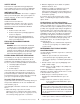
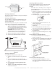
Figure 14
6. Correct all leaks at once.
7. Light heater (see Operating Your Heater, page
page 10.
Equipment
Shutoff Valve
Open
Closed
Pressure
Regulator
Heater
Cabinet
Ground Joint Union
Equipment
Shutoff Valve
From Gas Meter
(4” W.C. to 10.5”
W.C. Pressure)
Tee Joint
1/8” NPT Plug Tap
Cap
Pipe Nipple
Tee Joint
3/8” NPT Pipe Nipple
Sediment
Trap
Test Gauge
Connection
Reducer Bushing
to 1/8” NPT
3” Minimum
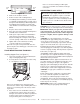
Control Valve
Equipment
Shutoff Valve
To gas meter