OPERATING INSTRUCTIONS AND OWNER’S MANUAL Model # MHVFGH30LPBT MHVFGH30LPT READ INSTRUCTIONS CAREFULLY: Read and follow all instructions. Place instructions in a safe place for future reference. Do not allow anyone who has not read these instructions to assemble, light, adjust or operate the heater. INSTALLER: Leave this manual with the appliance. CONSUMER: Retain this manual for future reference.
IMPORTANT WARNING: • WARNING: Do not use any accessory not • WARNING: • • • • • • CONTENTS WARNINGS........................................................................2 SPECIFICATIONS ................................................................ 3 PRECAUTIONS ...................................................................3 IGNITION SYSTEM BATTERY INSTALLATION ......................4 BLOWER FAN CONTROL SWITCH OPERATION ...................
SPECIFICATIONS 30,000 LP-Gas Only Yes Sides **Operating heater above elevations of 4,500 feet could cause pilot/ODS to shutdown heater.** PRECAUTIONS: Operating heater above elevations of 4,500 feet could cause pilot/ODS to shutdown heater.
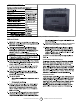
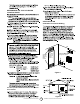
Product Features Ignitor Button Fan Blower Switch (located on back of heater) FRESH AIR FOR COMBUSTION AND VENTILATION WARNING Control Knob Burners ESTABLISHING ADEQUATE VENTILATION Grill National Fuel Gas Code, NFPA 54/ ANSI Z223.1, Section 5.
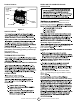
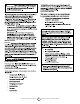
DETERMINING THE TYPE OF HEATER LOCATION SPACE: - Note: VENTILATION AIR Ventilation from Inside Building - WARNING: 12” National Fuel Gas Code, NFPA 54/ ANSI Z223.1, Ventilation Gills into Adjoining Room Option 1 Or remove door into Adjoining Room Option 3 Ventilation Gills into Adjoining Room - Option 2 12” Figure 2. OUTLET You must provide additional fresh air. Your options are as follows: Unvented LP-Gas Vent Free Heaters 5 Figure 3.
WARNING: LOCATING HEATER Ventilation from Outdoors • • • *IMPORTANT: CAUTION: IMPORTANT: Vent-free heaters add moisture to CAUTION: INSTALLATION NOTICE: - WARNING: • WARNING: CHECK GAS TYPE Use only LP-gas.
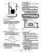
from sides Left Side Side WARNING: Maintain minimum clearances shown in Floor Figure 4 FASTENING HEATER TO WALL SEE CLEARANCE SPECIFICATIONS ON PG. 3 Mounting Bracket Figure 5 Adjoining Wall - Mounting Bracket 16” (Lg) 12-9/64” (Sm) Mark mounting hole locations and drill holes where indicated. Allow for minimum clearances 18” Min.
Figure 8. FLOOR MOUNTING AWAY FROM WALL: - Horizontal Slots Figure 11 Mounting Bracket mounted to wall Figure 9.
CAUTION: IMPORTANT: CHECKING GAS CONNECTIONS WARNING: WARNING: CAUTION: PRESSURE TESTING GAS SUPPLY PIPING SYSTEM Figure 12 IMPORTANT: CAUTION: LP-Gas - Unvented LP-Gas Vent Free Heaters 9 Installation Instructions and Owner’s Manual
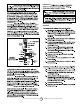
Pressure Testing Heater Gas Connections: - Caution: to disconnection errors can Operating Your Heater ance Figure 15 To Turn OFF Gas to Appli- ELECTRICAL WIRING DIAGRAM: o WARNING: Open Equipment Closed OPERATING YOUR HEATER FOR YOUR SAFETY READ BEFORE LIGHTING WARNING: If you do not follow these instructions Figure 13 Control Valve WHAT TO DO IF YOU SMELL GAS • • • Do not touch any electrical switch; do not use any To regulated propane source Equipment • • - Figure 14 Unvented LP-Gas Ve
THERMOSTAT CONTROL OPERATION - LIGHTING INSTRUCTIONS - wise TO TURN OFF GAS TO APPLIANCE to the OFF Note: INSPECTING BURNER Ignitor Button PILOT FLAME PATTERN Control Knob • Figure 16 • • Appliance To Turn OFF Gas to - Figure 17 • Unvented LP-Gas Vent Free Heaters 11 Installation Instructions and Owner’s Manual
CLEANING AND MAINTENANCE WARNING: • CAUTION: Exterior clean • WARNING: • Pilot Air Inlet Hole Figure 18 Unvented LP-Gas Vent Free Heaters 12 Installation Instructions and Owner’s Manual
TROUBLESHOOTING NOTE: WARNING: CAUTION: WARNING: • • • • • IMPORTANT: - - - Unvented LP-Gas Vent Free Heaters 13 Installation Instructions and Owner’s Manual
Only] - - - tion - - ture - - dows - Unvented LP-Gas Vent Free Heaters 14 Installation Instructions and Owner’s Manual
PARTS LIST AND DIAGRAM MODEL: MHVFGH30LPBT / MHVFGH30LPT ITEM P/N PART DESCRIPTION QTY ITEM P/N PART DESCRIPTION QTY 1 80041 Wire Guard 1 15 80081 Thermostat Valve 1 2 80116 Front Panel 1 16 N/A Thermostat Mounting Bracket 1 3 80025 Reflector 1 17 N/A Back Heat Shield 1 4 80029 Heat Shield 1 18 80058 Floor Mount Feet 1 5 80111 Steel Panel 1 19 80117 Back Panel 1 6 N/A Steel Panel Bracket 1 20 80037 Wall Mounting Bracket 1 7 80018 Burner Assembly 1
OPERATING INSTRUCTIONS AND OWNER’S MANUAL READ INSTRUCTIONS CAREFULLY: Read and follow all instructions. Place instructions in a safe place for future reference. Do not allow anyone who has not read these instructions to assemble, light, adjust or operate the heater. WARNING: USE ONLY MANUFACTURER’S REPLACEMENT PARTS. USE OF ANY OTHER PARTS COULD CAUSE INJURY OR DEATH. REPLACEMENT PARTS ARE ONLY AVAILABLE DIRECT FROM THE FACTORY AND MUST BE INSTALLED BY A QUALIFIED SERVICE AGENCY.