Installation, Operation and Maintenance Manual Steambath Generator Systems Residential Models: MS90E – MS400E and MSSUPER1E – 6E mr.steam ® Feel Good Inc. ® ! CAUTION This installation, operation and maintenance manual is for general reference. The installation, operation and maintenance manual supplied with the product must be used for installation, operation and maintenance purposes.
When installing and using this electrical equipment, basic safety precautions should always be followed, including the following: READ ME FIRST! ! WARNING As you follow these instructions, you will notice warning and caution symbols. This blocked information is important for the safe and efficient installation and operation of this generator.
RESIDENTIAL STEAMBATH GENERATOR SYSTEMS INSTALLATION, OPERATION MODEL _______________________________ & MAINTENANCE MANUAL MODELS: MS-90E, MS-150E, MS-225E, MS-400E, MS-SUPER 1E, MS-SUPER 2E, MS-SUPER 3E, MS-SUPER 4E, MS-SUPER 5E, MS-SUPER 6E TABLE OF CONTENTS Important Safety Instructions . . . . . . . . . . . . . Inside front cover Select Your MrSteam Model . . . . . . . . . . . . . . . . . . . . . . . . . . 2 Generator Specification Chart . . . . . . . . . . . . . . . . . . . . . . . . .
mr Installation, Operation & Maintenance Manual .steam __________________________________________________________________________ ® SELECT YOUR MRSTEAM ! WARNING In considering the purchase or use of this steambath system, please note that if you are pregnant, have a coronary condition, are in poor health, are being treated for any other medical condition, or are using medication or drugs, MrSteam recommends that you obtain the approval of a physician before use.
® BEFORE INSTALLING ume and construction. If any questions, please refer to MrSteam sizing and selection guide on page 2. Carefully inspect the Steam Generator and packaging for shipping damage. In the event of shipping damage, please contact the carrier for claim information. Our customer service department can assist you with any missing or damaged parts. 3. Marble or glass walls or ceilings.
I N S TA L L E R mr Installation, Operation & Maintenance Manual .steam __________________________________________________________________________ ® WATER QUALITY INFORMATION For optimum results, the water supply should be tested prior RECOMMENDED FEEDWATER QUALITY Hardness, ppm 8 – 85 (~0.5 – 5 gpg) P-Alkalinity, ppm 85 – 410 (~5 – 24 gpg) T. Alkalinity, ppm 200 – 500 (~7 – 0 gpg) pH (strength of alkalinity) 8.0 – 11.4 to installation.
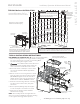
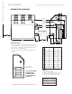
® TYPICAL MRSTEAM INSTALLATION ! CAUTION The control features an integral temperature sensor. Locate the control in a location representative of the desired steambathing temperatures. Do not locate the control above or near the steam head or direct steam emissions. NOTE: Drawings for illustrative purposes only. Consult with qualified designer, architect or contractor for steam room construction details.
I N S TA L L E R mr Installation, Operation & Maintenance Manual .steam __________________________________________________________________________ ® INSTALLATION STEAM OUTLET (1⁄2" NPT) PLUMBING 1. DO NOT install any valve in steam line. Flow of steam must be unobstructed. 2. Use 1/2-inch brass pipe or copper tubing from unit to steam head as permitted by codes. 3. Insulate steam line with fiberglass pipe insulation or similar insulation rated 212° F or higher. 4.
® INSTALLING THE ROUND OR SQUARE AROMASTEAM STEAMHEAD (1⁄2" NPT) 1/8" minimum clearance required when Acrylic Shield is used. NOTE: A 1 ⁄2" clearance hole around the steam pipe is needed to mount the steamhead. STEP 1 Locate steam head 6-12 inches above floor, except for: 1. Tub/shower enclosures, install 6 inches above tub top edge. 2. For enclosures with acrylic or other non-heat resistant flooring install Acrylic Shield Part Number MS-103938. 3.
I N S TA L L E R mr Installation, Operation & Maintenance Manual .steam __________________________________________________________________________ ® GENERATOR DIAGRAM D Water Inlet Control & Accessory Connections Steam Outlet Safety Valve Optional AutoFlush Manual Drain Valve ” for servicing J IMPORTANT NOTES: Provide a minimum of (12) inches at both ends and top of the steam generator or as required for servicing.
® ELECTRICAL CHART ________________________________________________________________________________________________________ ELECTRICAL Vol Max Room Model No. (Cu. Ft.
I N S TA L L E R mr Installation, Operation & Maintenance Manual .
I N S TA L L E R mr Installation, Operation & Maintenance Manual .steam __________________________________________________________________________ ® INSTALLATION INSTRUCTIONS FOR MODELS: MS-SUPER 4E, MS-SUPER 5E AND MS-SUPER 6E 1. Install each unit as in a single installation. Install the two generators as close to each other as possible. 2. ! WARNING Shock Hazard. Power must be disconnected at the main electrical supply before removing steam generator covers. 3.
I N S TA L L E R mr Installation, Operation & Maintenance Manual .steam __________________________________________________________________________ ® INITIAL START-UP AND CHECKOUT 1. Turn on control. Follow specific instructions provided with controls. 2. Steam will begin to appear in approximately 5 minutes (unless equipped with factory-installed Express Steam option) at the steam head.
® SYSTEM STATUS CODES The control (either iSteam®, AirTempo®, iTempo® or iTempo/Plus®) may display a status code if the steam generator is not functioning properly. Code H20 Code Meaning Water level is not satisfied within 5 min. Prr1 or Prr2 Temperature Probe Error Err1 Err2 Probable Cause Suggested Remedy Water Supply is off Turn on Water Supply Defective water feed solenoid Check/replace water solenoid valve Water feed probe not functioning Check/clean probe. Check probe wiring.
I N S TA L L E R mr Installation, Operation & Maintenance Manual .steam __________________________________________________________________________ ® OPTIONAL AUTOFLUSH® Steam Generator Box Contents AutoFlush Valve with Cord Installation Instructions. 3 Pin Connector for AutoFlush OPERATION The optional AutoFlush System feature automatically drains the MrSteam generator following each use.
® OPTIONAL DRIP PAN MrSteam strongly recommends the use of a drip pan in the unlikely event of a plumbing leak. Locate the drip pan on a solid level surface and place the steam generator inside the drip pan. Insure the steam generator is level (see page 4 for locating the steam generator). All plumbing shall be performed by a qualified licensed plumber and in accordance with applicable national and local codes. Check local plumbing code for receptor, trap and vent requirements. Drip pans drain by gravity.
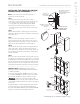
I N S TA L L E R mr Installation, Operation & Maintenance Manual .steam __________________________________________________________________________ ® PARTS IDENTIFICATION DIAGRAMS Contactor Liquid Level Control Board MS REGULAR MODELS Liquid Level Probe MS65E - MS400E (with AutoFlush®) shown with cover removed Transformer Water Feed Solenoid Power Supply Knock-Out Water Inlet Plug and Play Connection (see page 13) Steam Outlet Access Cover NOTE: FOR ILLUSTRATIVE PURPOSES ONLY.
® REPLACEMENT PARTS LIST _________________________________________________________________________________________________ Part No. Description Generator 99178MS 99297 100479 10477-3 103975 103904 103917 103990-60 104117-30 104117-60 MSTS Drain Valve Safety Valve 15PSI Water Feed Solenoid Valve w/filter Transformer 24VAC Liquid Level Control Board Tandem Cable for 2 generators (12 ft.) Tandem Cable for up to 5 generators (30 ft.) Cable for iTempo Control (60 ft.
I N S TA L L E R mr Installation, Operation & Maintenance Manual .steam __________________________________________________________________________ ® CONTROL INSTALLATION Refer to Control Manual for specific installation requirements BEFORE INSTALLING Turn power to the steam generator OFF before connecting the control to the generator. Failure to turn the power off will result in an inoperable control.
mr.steam Installation, Operation & Maintenance Manual __________________________________________________________________________ ® H O M E O W N E R READ ME FIRST! ! WARNING As you follow these instructions, you will notice warning and caution symbols. This blocked information is important for the safe and efficient installation and operation of this generator.
HOMEOWNER mr Installation, Operation & Maintenance Manual .steam __________________________________________________________________________ ® CARE TIPS FOR ALL CONTROLS AND STEAMHEADS SETTING THE STEAM BATH TEMPERATURE AND DURATION 1. Use only mild soap and water on a soft cloth to clean the control and steamhead. 2. DO NOT use abrasive cleansers. 3. If the decorative cover is damaged on the iTempo or iTempo/Plus call MrSteam technical service for replacement parts.
® ® USING MRSTEAM ESSENTIAL OILS Enjoy AromaSteam essential oils by placing a drop or two into an unheated AromaSteam steamhead as shown in the illustration. Only use MrSteam AromaSteam essential oils in the MrSteam AromaSteam steamhead. AromaSteam 10ml bottle with integrated dropper ! WARNING Essential oils and/or aroma therapy can cause inflammation, burns, headache, nausea and allergic reactions. Consult a physician before using aroma therapy. Recess for essential oil ! CAUTIONS 1.
mr.steam ® Feel Good Inc. ® www.mrsteam.com Products, information and specifications are subject to change without notice. Please call Sales & Support at 1.800.76.STEAM (East Coast) or 1.800.72.STEAM (West Coast) for more information. mr.steam ® Sussman-Automatic Corporation® I hello@mrsteam.com I www.mrsteam.com 9410 S. La Cienega Blvd.