
Instructions / Assembly
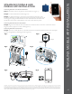

STEAMLINX MOBILE APP INSTALLATION
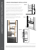
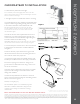
Connecting SteamLinx A to the Steam Generator
Step 1. Disconnect power to the generator at the breaker box
(gure 1).
Step2. Locate the SteamLinx Module (gure 2).
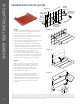
Step3. On Steam Generator- remove knock-out. Remove generator cover.
Route the SteamLinx A cable through the knockout. (gure 3). Locate the circuit
board (gure 4). Plug the SteamLinx A into the white connector located at the
far left side of the circuit board. Replace cover and screws. Restore power.
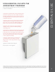
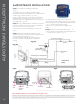
Connecting SteamLinx B to the Home Router
Step4. Plug the blue ethernet cable provided, into an ethernet slot on the back of the home router.
Plug the power supply into a 120V outlet. (gure 5).
Connecting SteamLinx to the Internet
Step5. Insure the mobile device is on the WiFi network. Download the SteamLinx App from the Apple
Store or Google Play by following prompts. (gure 6).
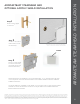
STEAMLINX MODULE AND
MOBILE APP INSTALLATION
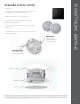
Mounting Tab
Indicator Light
SteamLinx A
Circuit Board
A
––––––––––––
GENERATOR
Cover
Screws
Generator
Cover
Knock-out in
the Generator
Jacket
A
––––––––––––
GENERATOR
Circuit
Board
Home Router
Power Supply SteamLinx B
Ethernet
Cable (3’)
Reset
Button
(troubleshooting
only)
3’ Cable
Mounting Tab
Indicator Light
SteamLinx A
Circuit Board
A
––––––––––––
GENERATOR
Cover
Screws
Generator
Cover
Knock-out in
the Generator
Jacket
A
––––––––––––
GENERATOR
Circuit
Board
Home Router
Power Supply SteamLinx B
Ethernet
Cable (3’)
Reset
Button
(troubleshooting
only)
3’ Cable
Mounting Tab
Indicator Light
SteamLinx A
Circuit Board
A
––––––––––––
GENERATOR
Cover
Screws
Generator
Cover
Knock-out in
the Generator
Jacket
A
––––––––––––
GENERATOR
Circuit
Board
Home Router
Power Supply SteamLinx B
Ethernet
Cable (3’)
Reset
Button
(troubleshooting
only)
3’ Cable
Mounting Tab
Indicator Light
SteamLinx A
Circuit Board
A
––––––––––––
GENERATOR
Cover
Screws
Generator
Cover
Knock-out in
the Generator
Jacket
A
––––––––––––
GENERATOR
Circuit
Board
Home Router
Power Supply SteamLinx B
Ethernet
Cable (3’)
Reset
Button
(troubleshooting
only)
3’ Cable
Mounting Tab
Indicator Light
SteamLinx A
Circuit Board
A
––––––––––––
GENERATOR
Cover
Screws
Generator
Cover
Knock-out in
the Generator
Jacket
A
––––––––––––
GENERATOR
Circuit
Board
Home Router
Power Supply SteamLinx B
Ethernet
Cable (3’)
Reset
Button
(troubleshooting
only)
3’ Cable
Mounting Tab
Indicator Light
SteamLinx A
Circuit Board
A
––––––––––––
GENERATOR
Cover
Screws
Generator
Cover
Knock-out in
the Generator
Jacket
A
––––––––––––
GENERATOR
Circuit
Board
Home Router
Power Supply SteamLinx B
Ethernet
Cable (3’)
Reset
Button
(troubleshooting
only)
3’ Cable
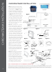
Fig 1. Fig 2.
Fig 3. Fig 4.
Fig 5. Fig 6.
29
IMPORTANT The information in this guideline is designed to provide a general overview of how MrSteam products are installed. The diagrams are for Illustrative purposes only. NEVER use this document for the Installation,
Operation or Maintenance of any MrSteam product. For Installation, Operation and Maintenance information, only use the specic Installation, Operation and Maintenance manual supplied with each Mr. Steam product. The
specic Installation, Operation and Maintenance manual that is supplied with each Mr. Steam product contains important information required for the safe and reliable installation and operation of the product. Failure to use
the specic Installation, Operation and Maintenance manual that is supplied with each Mr. Steam product may result in product damage, property damage, death or personal injury. If you do not have an Installation, Operation
and Maintenance manual please contact MrSteam for a free copy, or download a copy from www.mrsteam.com. If you have any questions about the installation, operation or maintenance of any MrSteam product please
contact a customer or technical service representative using the contact information on the back cover of this guideline.