
Installation Guide


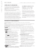


TYPICAL INSTALLATION INSTRUCTIONS
FOR MODELS MS SUPER 4E, 5E & 6E
(shown with optional AutoFlush)
1. Install each steam generator as in a single installation. Install genera-
tors as close as practical to each other, not exceeding 10 feet.
The interconnecting cable length is 12 feet.
2. Shock Hazard. Power must be disconnect-
ed at the main electrical supply. Remove steam gen-
erator covers. Retain screws and covers for reuse.
3. Connect the iSteam
®
or AirTempo
®
control to either
unit as per the Installation Manual supplied with
each control.
4. Remove one knock-out on each generator as shown.
Insert the ends of interconnecting cable provided
(PN 103904) through the knock-outs as shown in
diagram. Connect each end to the printed circuit
board connector labeled "TANDEM" as shown.
5. Prevent the interconnecting cable from contacting
hot surfaces such as steam outlet, safety valve
and the like.
6. Connect separate plumbing and power supplies
for each unit. Replace covers with cover screws.
7.
Provide unions as required to facilitate installation
and disconnection of piping
NOTE: The secondary unit will de-energize when the
steam room reaches steambathing temperature resulting
in a more gentle and energy efficient operation.
Printed Circuit Board Component
shown enlarged for illustrative purpose.
Primary Unit
Interconnecting
Cable
PN 103904
Control
Cable
Secondary Unit
iSteam or
AirTempo
Control
Optional AutoFlush
®
, see AutoFlush
Installation page 14
Steam Heads
shown with
optional acrylic
shields
Water Feed
Line
Power
Supply
NOTE: Drawings for illustrative purposes only.
Consult with qualified designer, architect or
contractor for steam room construction details.
Provide unions as required to facilitate
installation and disconnect of piping
Steam
Generator
Field installed
power supply
Field installed
steam supply pipe
Drain Valve must be closed
when the optional
AutoFlush is not installed
Control cable run in
1” conduit (located
behind the wall)
Steam Head (shown with optional acrylic shield)
See page 7 for Steam Head Installation information
iSteam
®
, AirTempo
®
or iTempo
®
Control
Refer to Control
Installation Manual
for installation
information
Field installed
water supply line
The control features an integral
temperature sensor. Locate the control in a location
representative of the desired steambathing temper-
atures. Do not locate the control above or near the
steam head or direct steam emissions.
TYPICAL MRSTEAM INSTALLATION
When installing the optional AromaSteam, install a down-
ward facing 90-degree T in the steam supply line. See the
AromaSteam Installation Manual for complete information.
To avoid unintentional steambath operation, do not locate the control
where other controls, accessories, shower heads, valves, body sprays or similar within the
shower could cause confusion or interfere with the MrSteam control’s intended use and function.
5
I N S T A L L E R
mr
.
steam
®
Installation, Operation & Maintenance Manual
__________________________________________________________________________
All drawings are for illustrative purposes only
WARNING
!
CAUTION
!
CAUTION
!