
Installation Guide

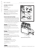


TROUBLESHOOTING
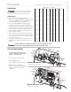
IMPORTANT NOTE: The model and serial number is printed on
the data plate on the front of the steam bath generator.
Step 1 Check main incoming power to the unit.
Step 2 Ensure the black wires from the pri-
mary side of the transformer are connected
to the quick connect tabs on the line side
of the contactor.
Step 3 Verify that you have 24VAC
coming out of the transformer, WHT &
WHT/BLU wires, into the board.
Step 4 Verify that you have the green
light on the PC board.
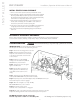
Step 5 Push the white test button to
run the generator for 10 minute test
cycle. Make sure the steam room is
empty.
Step 6 Verify that you have 24 VAC to the water feed
solenoid, GRY & WHT/GRY wires (will fill when needed).
Step 7 Temporarily short out the WLS (Purple wire) and GND (Green wire) ter-
minals and verify the contactor engages.
Step 8 When the red light is on, verify 24 VAC,
RED & WHT/RED wires, to the contactor.
Step 9 Check main voltage on the
load side of the contactor when it is engaged.
Step 10 If all steps on the power path were verified, turn off power to the unit
and pull the heating element via the left hand access panel for inspection.
INITIAL START-UP AND CHECKOUT
1. Turn on control. Follow specific instructions provided with controls.
2. Steam will begin to appear in approximately 5 minutes (unless equipped
with factory-installed Express Steam option) at the steam head. Steam
will shut off when desired temperature is reached and will automatically
resume when room temperature drops below set point.
3. Steam will shut off automatically when control counts down to zero.
To shut steam off manually, turn control OFF. To clear steam from
enclosure area, turn shower on before opening door.
4. If unit does not start and control does not turn ON (control display does
not light up) then turn breaker off for 20 seconds and try again.
5. Check all internal and external plumbing fittings for leaks while the
steam is on.
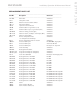
OPTIONAL & ACCESSORY EQUIPMENT
Refer to specific instruction manual for installation, operation and maintenance of optional equipment and
accessories such as iSteam
®
, AirTempo
®
, iTempo/Plus
®
, iTempo
®
, Home Wizard
®
, iGenie
®
and MSTS.
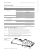
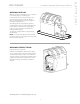
DO NOT disassemble internal components,
All drawings are for illustrative purposes only
internal components contain no serviceable parts.
12
I N S T A L L E R
mr
.
steam
®
Installation, Operation & Maintenance Manual
__________________________________________________________________________
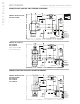
All electrical troubleshooting to be performed by a qualified licensed electrician
1
2
4
7
8
9
3
6
5
Transformer
Liquid Level
Control Board
Water Feed
Solenoid
Ste
Ou
Liquid
Level Probe
AutoFlush
and Play
Connectio
Contactor
Power Supply
Knock-Out
Field Wiring
Water Feed
WARNING
!