
Installation Guide


mr
.
steam
®
Installation, Operation & Maintenance Manual
__________________________________________________________________________
I N S T A L L E R
13
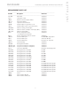
SYSTEM STATUS CODES
The control (either iSteam
®
, AirTempo
®
, iTempo
®
or iTempo/Plus
®
) may display a status code if the steam generator is not functioning
properly.
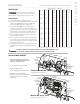
Code Code Meaning Probable Cause Suggested Remedy
H20 Water level is not Water Supply is off Turn on Water Supply
satisfied within 5 min.
Defective water feed solenoid Check/replace water solenoid valve
Water feed probe not functioning Check/clean probe.
Check probe wiring.
Drain Valve Open Check/Close drain valve
AutoFlush not functioning Check/Replace AutoFlush
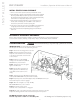
Prr1 Temperature Probe Error Control cable/MSTS cable cut Replace control cable/MSTS
or Prr2
Internal problem with control/MSTS Replace control / MSTS
Err1 Incorrect Field Supply Voltage Incorrect voltage supplied Supply steam generator with the correct
(green light on liquid level to Generator voltage noted on the data plate label.
control board will be off)
Err2 Button on control is pressed Control cover misalignment Remove and reinstall control cover
for more than 5 minutes
Debris behind control cover Remove control cover and clean cover,
control and keypad with a damp cloth
Errb Water level not satisfied in a tandem set up - Check secondary generators, see H20.
Err7 Liquid Level Control Board malfunction Memory error in LLCB Press ON/OFF to clear.
Replace control if code remains.
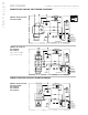
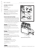
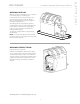
LIQUID LEVEL CONTROL BOARD Explanation of LED Indicators
______________________________________________________________________________________________________________________________________
GREEN LED is ON when there is 208/240 Volt incoming power connected,
24 Volt transformer secondary output and on-board 5 Volt DC control power are present.
______________________________________________________________________________________________________________________________________
YELLOW Water level indicator–LED is OFF when no water is detected (for more that 5 seconds). ON when
water level is satisfactory. For units with AutoFlush, if more than five hours have elapsed since
last usage and this LED is ON it is indicative of an AutoFlush or water level probe circuit malfunction.
______________________________________________________________________________________________________________________________________
RED Contactor relay indicator–LED is ON when relay is closed and sending 24 Volts to the
contactor coil. (This LED comes ON if the generator is ON.)
______________________________________________________________________________________________________________________________________
FORCE ON Press this button to operate the generator. This button is for trouble shooting only and will operate
TEST BUTTON
if a control is connected or not. Pressing the button again will shut the generator OFF. The test button
will only allow the generator to operate for 10 minutes.
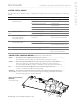
Liquid Level Control Board
PN 103975
(shown without wiring)
RED (Heater)
YELLOW (Water Level)
GREEN (Power)
Force On
Test Button
All drawings are for illustrative purposes only