QUICK SET UP GUIDE GENERATOR | CONTROLS | ACCESSORIES Feel Good Inc®.
For Illustrative purposes only.
CONTENTS GENERATOR LOCATION 5 POWER CONNECTION 6 WATER FEED 7 STEAM OUTLET 7 DRAIN LINE 7 AUTOFLUSH 8 ® CONDENSATION PAN 9 LIQUID LEVEL CONTROL BOARD 9 MAX GENERATOR INSTALLATION 10 GENERATOR STEAM CONTROL LOCATION 11 15 STEAMHEAD INSTALLATION LOCATION 16 iSTEAM 3 CONTROL INSTALLATION 17 AIRTEMPO CONTROL INSTALLATION 19 ® ® AIRTEMPO® WIRELESS RECEIVER/ FLUSH MOUNT INSTALLATION 20 iTEMPO OR ITEMPO/PLUS CONTROL ® ® INSTALLATION 23 REMOTE TEMPERATURE PROBE INSTALLATION 24
KEY SIGNAL WORDS WARNING As you follow these instructions, you will notice warning and caution symbols. This blocked information is important for the safe and efficient installation and operation of this generator. These are types of potential hazards that may occur during installation and operation: WARNING Indicates a potentially hazardous situation, which, if not avoided, could result in death or serious injury.
MRSTEAM® GUIDE MR.STEAM® GENERATOR INSTALLATION LOCATING THE MR.STEAM® GENERATOR Select a location as near as practical to the steam room. Typical locations include: closet, vanity cabinet, climate controlled attic or basement. Locate steambath generator as close to shower as possible. 30ft cable is included. Optional 60ft cable available WARNING The information in this guide is designed to provide a general overview of how MrSteam® products are installed.
MRSTEAM® GUIDE FIELD POWER SUPPLY CONNECTION Please refer to the wiring diagram in the Mr.Steam Installation Manual for complete wiring information. MAIN ELECTRICAL DISCONNECT PANEL HIGH VOLTAGE POWERLINE TO AVOID EQUIPMENT DAMAGE DO NOT CONNECT POWER SUPPLY DIRECTLY TO THE HEATING ELEMENTS!!! WARNING The information in this guide is designed to provide a general overview of how MrSteam® products are installed.
MRSTEAM® GUIDE WATER FEED 1. Connect to cold water line. WATER FEED LINE (3/8” NPT) 2. Provide a shut off valve, and a copper or brass union on the water supply line. 3. Flexible copper tubing, braided hose, PVC or PEX if permissible by local codes. STEAM OUTLET PIPE 1. Provide a 1/2” copper or brass union on steam line. 2. Pitch steam line 1/4” per foot towards steam head or steam generator to avoid valleys and trapping of condensate.
MRSTEAM® GUIDE OPTIONAL AUTOFLUSH® OPERATION The optional AutoFlush® System automatically drains the Mr.Steam® system following each use. A time delay allows the water to cool down (about two hours) before it drains by gravity for a safe and gentle operation.
MRSTEAM® GUIDE CONDENSATION PAN DO NOT PLUMB THE GENERATOR DRAIN AND CONDENSATION PAN DRAIN TOGETHER GENERATOR DRAIN 3/4” OUTLET CONDENSATION PAN TO BE PLUMBED SEPARATELY LIQUID LEVEL CONTROL BOARD 1 2 3 4 6 5 7 11 10 9 8 1 ChromaSteam3 Cable Connection 2 SteamLinx A Cable Connection 7 Tandem Connection (for two generators) 3 AudioSteam3 Cable Connection 8 Test Button 4 AromaSteam 1/4” Spade Terminal Connection 9 Control Cable Connection 5 Chroma72 1/4” Spade Terminal Connect
MRSTEAM® GUIDE NEW MAX STEAM GENERATOR INSTALLATION (MX 4E, 5E & 6E) DO NOT INSTALL IN VANITY OR OTHER SMALL SPACES 3/4” STEAMLINE MUST HAVE TWO STEAM HEADS ONE 27 1/2” LINEAR STEAMHEAD CAN ALSO BE USED LARGE ROOM CAPACITY MAX GENERATORS REPLACE MS SUPER 4E, 5E, 6E TWO GENERATOR CONFIGURATIONS 1” DRAIN Refer to the Mr.Steam MAX Installation manual for additional installation information.
MRSTEAM® GUIDE TYPICAL MS GENERATOR 5 1 2 12 4 3 13 8 9 14 6 7 10 11 1 Contactor 2 Transformer 3 Liquid Level Control Board 9 Safety Valve 4 Liquid Level Probe 10 Drain Valve 5 Water Feed Solenoid 11 Stainless Steel Tank 6 Heating Element 12 Water Inlet 7 Express Steam Heater (optional) 13 Plug & Play Connection 8 Steam Outlet 14 Element Access Cover For Illustrative purposes only.
MRSTEAM® GUIDE Product Dimensions* MS Generators 14 1/2” x 14 3/4” x 6 3/4” ″ Total Room Volume (cu.ft.) kW Amps 240V/1PH Wire Size AWG‡ Water Usage Gallons†† MS90E up to 100 5 21 10 0.67 MS150 101-150 6 25 8 0.80 MS225E 151-225 7.5 32 8 1.0 MS400E 226-360 9 38 8 1.2 MSSUPER1E 361-475 10 42 8 1.4 MSSUPER2E 476-575 12 50 6 1.6 MSSUPER3E 576-675 15 63 4 2.0 MX4E 676-875 20 84 2 2.7 MX5E 876-1075 24 100 1 3.2 MX6E 1076-1275 30 125 2/0 4.
QUICK SET UP GUIDE CONTROLS For Illustrative purposes only.
For Illustrative purposes only.
MRSTEAM® GUIDE LOCATING THE iSTEAM®3, iTEMPO®, iTEMPO/PLUS® & AIRTEMPO® CONTROLS RUN CABLE THROUGH CONDUIT INSIDE WALL CAVITY. CABLE NOT REQUIRED WITH AIRTEMPO®. Locate control (or Remote Temperature Sensor) where it will sense general room temperature and NOT direct steam emission from the steam head. iSTEAM®3 Controls installed inside the steam room must be located 4-5 feet above the floor on a vertical wall.
MRSTEAM® GUIDE STEAMHEAD INSTALLATION LOCATION GOOD STEAM CONTROL IMPORTANT NOTE: To avoid unintentional steam bath operation, do not locate the control where other controls, accessories, shower heads, valves, body sprays or similar within the shower could cause confusion or interfere with the MrSteam control’s intended use and function.
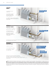
MRSTEAM® GUIDE iSTEAM®3 CONTROL INSTALLATION IMPORTANT NOTE: Turn power to the steam generator OFF before installing the control. Failure to turn the power off will result in an inoperable control. 1A STEP 1 PLUG the 30’ control cable into the iSteam®3 control pigtail (1A). Turn the generator on and test the control to verify proper function. Install rough-in box in desired control location. Use rough-in box provided as a guide to cut hole in finished wall.
MRSTEAM® GUIDE 2A STEP 2 Peel the adhesive film off the back of the iSteam control (2A). Apply a bead of silicone (provided) around the rear of the control as required to create a moisture seal (2B). Ensure the control is level. Carefully feed the cable into the rough-in box and secure the control to the wall. Care must be taken to not pinch the cable. 2B Remove and discard the peel off screen protector (2C).
MRSTEAM® GUIDE AIRTEMPO® SURFACE MOUNT INSTALLATION A B STEP 1 Determine the desired installation location of the control. The AirTempo controls are designed to be installed inside or outside the steam room as a matter of personal preference. STEP 2 • Remove the surface mount bayonet from the back of the AirTempo Control (A). • Remove and discard the release paper to expose the adhesive liner (B). BAYONET 4-5 ft STEP 3 • Ensure the mounting surface is clean, flat/smooth, and dry.
MRSTEAM® GUIDE AIRTEMPO® WIRELESS RECEIVER INSTALLATION The control can be located up to 60 feet from the wireless receiver. Construction materials may affect the communication between the control and the receiver. Test the range of the AirTempo®. It may be necessary to change the location of the wireless receiver to improve the range. Contact your local MrSteam® representative (https://www.mrsteam.com/find-a-dealer) for an optional 30 or 60 foot cable.
MRSTEAM® GUIDE STEP 2 Remove decorative bezel from AirTempo® control. IMPORTANT NOTE: BE CAREFUL NOT TO DROP CONTROLLER WHEN RING POPS OFF STEP 3 • Using the template provided, cut the hole in the desired location. Do not oversize or undersize the cutout. Ensure the template is level before cutting the hole. • Test fit the flush mount box to ensure the hole is the correct size. • Ensure the mounting surface is clean and dry.
MRSTEAM® GUIDE STEP 5 Place the electronic assembly into the decorative bezel as shown. STEP 6 The retention ring snaps onto the assembly from behind. The 3 piece assembly can then be placed into the flush mount box. WARNING The information in this guide is designed to provide a general overview of how MrSteam® products are installed. All images and diagrams are for illustrative purposes only and may have been altered for presentation purposes.
MRSTEAM® GUIDE iTEMPO OR iTEMPO/PLUS CONTROL INSTALLATION IMPORTANT NOTE: Turn power to the steam generator OFF before installing the control. Failure to turn the power off will result in an inoperable control. STEP 1 Firmly connect the control cable to the control pigtail. Turn on power to the steam generator and test the control to verify correct connections. Test per instructions. Disconnect control cable. Make a 2-5⁄8” wide by 3-7⁄8” high cutout in the desired control location.
MRSTEAM® GUIDE REMOTE TEMPERATURE SENSOR (MSTS) A Remote Temperature Sensor is required when the control is installed outside the steam room. Locate the RemoteTemperature Sensor where it will sense general room temperature and NOT direct steam emission from the steam head. Refer to the MrSteam Installation manual for additional control installation information. For Illustrative purposes only. Consult with qualified designer, architect or contractor for steamroom construction details.
MRSTEAM® GUIDE FIG 2 STEP 4 With a minimal length of the cable exposed, apply silicone (provided) to the hole in the wall as required to create a moisture seal as shown in Fig 2. FIG 3 STEP 5 Push the Remote Temperature Probe into hole as required to leave between 1/4”- 1/2” of the probe. Exposed as shown in Fig 3. STEP 6 Ensure a minimum of 1/4” of the probe is exposed to the air. Failure to do so may result in an inoperative control and a hazardous condition.
MRSTEAM® GUIDE CONNECTING THE CONTROL CABLE TO THE STEAM GENERATOR Route the control cable (provided with the control) from the wall cutout to the steam generator. The 30’ (and optional 60’) control cable features identical Mini-Din connectors at both ends. CONTROL CABLE IMPORTANT NOTE: The standard length of the cable for connecting the control to the steam generator is 30 feet. The steam generator and control must be located accordingly. Contact a MrSteam® representative (https://www.mrsteam.
QUICK SET UP GUIDE ACCESSORIES
For Illustrative purposes only.
MRSTEAM® GUIDE AROMASTEAM SYSTEM Electronic Oil delivery system evenly infuses aroma into steam for an aromatherapy experience. Complete with oil container caddy, hoses, fittings and oil check valve. AromaSteam Essential oils are available in one-liter bottles. Not for use with acrylic or fiberglass rooms. DO NOT EXCEED 30 FEET OF TUBING OR A VERTICAL DISTANCE OF 6 FEET BETWEEN THE PUMP HEAD AND CHECK VALVE.
MRSTEAM® GUIDE AROMA TERMINALS REQUEST CABLE ,CABLES MUST NOT CONTACT STEAM PIPE. STEP 5 Plug the request cable from the AromaSteam into the steam generator’s PC board and plug the power cord into a 120 volt outlet. For Illustrative purposes only. Consult with qualified designer, architect or contractor for steamroom construction details. WARNING The information in this guide is designed to provide a general overview of how MrSteam® products are installed.
MRSTEAM® GUIDE AROMASTEAM STEAMHEAD STEP 1 Attach Locating Nipple to steam line. NOTE: Steamhead to be installed 6-12” above the finished floor. A 1.5” diameter hole in the steam room is required to mount the steamhead. Refer to the MrSteam Installation Manual for additional installation information. LOCATING NIPPLE STEAM LINE STEP 2 Provide a 1 1/2” diameter hole in finished wall to mount the steamhead.
MRSTEAM® GUIDE USING ESSENTIAL OILS WITH THE AROMASTEAM™ STEAMHEAD • Enjoy essential oils by placing a drop or two, into your steamhead as shown in the illustration. • Tightly close containers when storing oils. • Keep away from sources of ignition. For Illustrative purposes only. Consult with qualified designer,architect or contractor for steamroom construction details. WARNING 1. START WITH ONE DROP TO GAUGE STRENGTH AND SUITABILITY. LIMIT TO A MAXIMUM OF A FEW DROPS DURING A STEAMBATHING SESSION.
MRSTEAM® GENERAL GUIDE LINEAR STEAMHEAD Do not locate the steam head in any location where the steam emission zone is near a seat, bench, or any space occupied by any persons. for a diagram of the steam emission zone. For Illustrative purposes only. Consult with qualified designer, architect or contractor for steamroom construction details. STUD CEMENT BOARD THIN SET FINISHED SURFACE SILICONE NOTE: STEAMHEAD TO BE INSTALLED 6-12” ABOVE THE FINISHED FLOOR. REFER TO THE MR.
MRSTEAM® GUIDE STEP 1 Determine the location of the finisihed wall surface. Mount the steam head between two studs using the four slotted holes. Use a level to ensure steam head is level in both the horizontal and vertical positions. Position the steam head face to be flush or extend 1/8” from the finished wall surface. 3/4” NPT Steam line opening should be on top. DO NOT mount steam head upside down. STEP 2 Attach steam piping to the 3/4” NPT opening on the top of the linear steam head.
MRSTEAM® GUIDE CHROMASTEAM3 CONTROL BOX LED FIXTURE NOTE: FOR MOOD LIGHTING ONLY. STEP 1 Locating the control box. Determine the desired location of the ChromaSteam3 control box outside the steam room in a dry location. FIGURE 1 STEP 2 Installing the control box. Using screws and washers, affix the control box to a stable vertical surface (e.g., stud) using the mounting holes on either side of the control box (Figure 1). FIGURE 2 STEP 3 Install junction box.
MRSTEAM® GUIDE FIGURE 3 STEP 4 Connect the ChromaSteam3 fixture’s pigtail to the 30foot control cable in the junction box (Figure 3). FIGURE 4 STEP 5 Clean the surface of the ceiling to ensure the double-stick adhesive of the fixture bonds completely to the ceiling. Peel off and discard the protective layer from the fixture’s double-stick adhesive (Figure 4). FIGURE 5 STEP 6 Squeeze the retention springs on the back of the fixture and fit them into the junction box (Figure 5).
MRSTEAM® GUIDE STEP 8 Connecting ChromaSteam3 Fixture to ChromaSteam3 Control Box. Remove the two cover screws from the front of the control box and remove the cover from the unit. Insert the free end of the control cable into the control box’s LED receptacle (Figure 7). FIGURE 7 STEP 9 Connecting the ChromaSteam3 control box to the steam generator. Remove the cover and knockout on steam generator. Connect the controller cord directly to the steam generator’s circuit board (A in Figure 8).
MRSTEAM® GUIDE CHROMASTEAM 72 LIGHT FIXTURE STEP 1 Determine the placement of the light. LED CLUSTER IMPORTANT: DO NOT INSTALL THE FIXTURE ASSEMBLY (LIGHT) WHERE DIRECT CONTACT WITH STEAM OR WATER EMISSION COULD OCCUR. DO NOT INSTALL THE LIGHT IN A LOCATION WHERE IT COULD BECOME SUBMERGED. STEP 2 The light requires a 41⁄4”diameter hole for mounting. STEP 5 Connect the quick connect tabs to the control board in the generator at the location marked CHROMA.
MRSTEAM® GUIDE AUDIOSTEAM3 If using the wired input, connect a 1/8” (3.5 mm) stereo audio cord (not included) to the auxiliary output, and route the cable through the strain relief channel. Connect the free end of the audio cord to an audio source. STEP 4 Connect 10-pin MATE-N-LOK adapter with attached wires — to the speaker outputs. To operate the AudioSteam via iSteam3, you must connect the AudioSteam (Figure 2) to an internal connector in the steam generator.
MRSTEAM® GUIDE MS-SPEAKER • Two flush-mount two-way speakers for steam/shower use, polypropylene cones, ABS frames with grills. • Suitable for almost any source of audio input. • Rated 60W peak power 8 ohms impedance with 1” tweeter for full range sound. • Use only CL2 or CL3 UL listed wires to connect speakers to audio source. • Available in Round (6 1/2”) and Square (7”) in both white and black designs.
MRSTEAM® GUIDE STEP 2 Connect speaker wire STEP 3 Apply a bead of silicone to the speaker flange. SILICONE RTV BRACKETS (Rotate out for speaker installation in wall or ceiling) STEP 4 Place the speaker in the hole and tighten the screws on the integral mounting bracket to secure the speaker. WARNING The information in this guide is designed to provide a general overview of how MrSteam® products are installed.
MRSTEAM® GUIDE SHOWER SEAT STEP 1 Mount the WallSeat on a suitable surface like tile, granite or marble. Mount the seat at a height above the floor according to personal preference. STEP 2 Using the template provided, drill four pilot holes into the header and 4 clearance holes into the tile. Use a level to ensure pilot holes are level. Be precise. Do not oversize or undersize the pilot holes. Drill the pilot holes to the full 3” depth (length of the screws).
MRSTEAM® GUIDE FIGURE 2 STEP 4 Insert seat assembly to brackets. Place seat with the MrSteam logo on the bottom. Insert hinge pins to both left and right brackets while the seat assembly is in vertical position. Securely tighten both hinge pins, using Allen wrench provided (Figure 2).
MRSTEAM® GUIDE STEAMLINX® MODULE AND MOBILE APP FIGURE 1 STEP 1 Disconnect power to the generator at the breaker box (Figure 1). MOUNTING TAB FIGURE 2 STEP 2 Locate SteamLinx A adjacent to the steam generator, mount to a secure surface using the mounting tab provided. INDICATOR LIGHT WARNING The information in this guide is designed to provide a general overview of how MrSteam® products are installed.
MRSTEAM® GUIDE FIGURE 3 GENERATOR COVER STEP 3 Remove generator cover. Route the SteamLinx® A cable through the knockout (Figure 3). KNOCK-OUT IN THE GENERATOR JACKET COVER SCREWS FIGURE 4 STEP 4 Plug the SteamLinx® A cable into one of the white connectors located at the far left side of the circuit board. Replace cover and screws. CIRCUIT BOARD STEP 5 Plug the blue ethernet cable provided into an open ethernet port on the back of the router and the other end into SteamLinx® B.
MRSTEAM® GENERAL GUIDE TYPICAL INSTALL OF DREAM PACKAGE SCHEMATIC 1 AromaSteam System 5 iSteam®3 Controller 2 AudioSteam3 6 Speakers 3 ChromaSteam3 Control Box 7 ChromaSteam Fixture 4 SteamHead 8 Steamlinx® 6 2 7 6 5 3 8 STEAM ROOM (WET) 4 GENERATOR 1 WARNING The information in this guide is designed to provide a general overview of how MrSteam® products are installed. All images and diagrams are for illustrative purposes only and may have been altered for presentation purposes.
A leader and innovator in residential and commercial steam shower systems, spa products and experiences. CONTACT US HEADQUARTERS Sussman-Automatic Corporation® 43-20 34th Street Long Island City, NY. 11101 USA tel 1-800-76 STEAM (767-8326) WEST COAST Sussman-Automatic Corporation® 9410 South La Cienega Blvd Los Angeles, CA. 90301 USA tel 1-800-72 STEAM (727-8326) Or write to us at hello@mrsteam.com Mr. Steam, Mr. Steam and des.