
Owners Manual
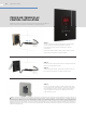
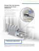


STEP 4
Apply a bead of silicone (provided) around the rear of
the control as required to create a moisture seal.
Remove and discard the release paper to expose the
adhesive liner.
Press the ush mount box against the wall until the
adhesive sticks and holds rmly.
WARNING The information in this guide is designed to provide a general overview of how MrSteam® products are installed. All images and diagrams are for illustrative purposes only
and may have been altered for presentation purposes. NEVER use this document for the Installation, Operation or Maintenance of any MrSteam® product. For installation, operation and
maintenance information and instructions, only use the applicable MrSteam® Installation, Operation & Maintenance Manual(s). The specific Installation, Operation & Maintenance manual
that is supplied with each MrSteam® product contains important information required for the safe and reliable installation and operation of the product. Failure to install any MrSteam®
product according to the applicable manual may result in property damage, an inoperable system/control, or hazardous condition. If you do not have the applicable Installation, Operation
& Maintenance manual please contact MrSteam® for a free copy, or download a copy from www.mrsteam.com. If you have any questions about the installation, operation or maintenance of
any MrSteam® product please contact a customer or technical service representative using the contact information on the back cover of this guide or consult a properly licensed contractor,
architect and/or design professional.
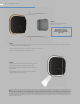
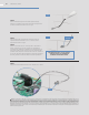
STEP 2
Remove decorative bezel from
AirTempo
®
control.
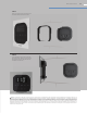
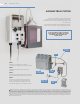
STEP 3
• Using the template provided, cut the hole in the desired location. Do not oversize or undersize the cutout. Ensure the
template is level before cutting the hole.
• Test t the ush mount box to ensure the hole is the correct size.
• Ensure the mounting surface is clean and dry.
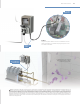
IMPORTANT NOTE: BE
CAREFUL NOT TO DROP
CONTROLLER WHEN RING
POPS OFF
21 MRSTEAM
®
GUIDE