
Owners Manual
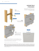
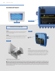
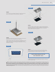
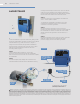

STEP 8
Connecting ChromaSteam3 Fixture to ChromaSteam3
Control Box. Remove the two cover screws from the
front of the control box and remove the cover from the
unit. Insert the free end of the control cable into the
control box’s LED receptacle (Figure 7).
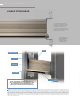
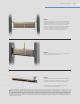
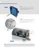
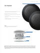
STEP 9
Connecting the ChromaSteam3 control box to the steam
generator. Remove the cover and knockout on steam
generator. Connect the controller cord directly to the
steam generator’s circuit board (A in Figure 8).
Plug the ChromaSteam3 control box power cord into a
120V grounded electrical outlet.
WARNING The information in this guide is designed to provide a general overview of how MrSteam® products are installed. All images and diagrams are for illustrative purposes only
and may have been altered for presentation purposes. NEVER use this document for the Installation, Operation or Maintenance of any MrSteam® product. For installation, operation and
maintenance information and instructions, only use the applicable MrSteam® Installation, Operation & Maintenance Manual(s). The specific Installation, Operation & Maintenance manual
that is supplied with each MrSteam® product contains important information required for the safe and reliable installation and operation of the product. Failure to install any MrSteam®
product according to the applicable manual may result in property damage, an inoperable system/control, or hazardous condition. If you do not have the applicable Installation, Operation
& Maintenance manual please contact MrSteam® for a free copy, or download a copy from www.mrsteam.com. If you have any questions about the installation, operation or maintenance of
any MrSteam® product please contact a customer or technical service representative using the contact information on the back cover of this guide or consult a properly licensed contractor,
architect and/or design professional.
FIGURE 7
FIGURE 8
A
37 MRSTEAM
®
GUIDE