
Installation Sheet

mr
.
steam
®
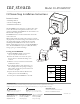
CU-Steamstop Installation Instructions
___________________________________________________________________________________
Wiring the CU-STEAMSTOP
Electric shock hazard.
Disconnect all power supplies at the main discon-
nect switch before proceeding. All electrical
wiring must be installed by a qualified, licensed
electricianin accordance with National and local
codes.
1. Route the cable provided (if more than 30
feet is needed standed 20 AWG wired may be
spliced to the provided cable) through non-
metalic condit from the steambath generator
to the CU-STEAMSTOP button.
Note: The end of the cable with the connector
shall be located at the steam generator.
2. Connect the bare ends of the cable to the
internal switch mechanism in the CU-STEAM
Stop.
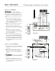
3A. For CU Boilers Equipped with Digital 1
Controls: Connect the wire to the connector
on the back of the Digital 1 control, as shown
in the wiring Diagram A.
3B. For boiler equipped with F1 Plus controls:
Splice the wire from the CU-STEAMSTOP into
the each leg of the temperature probe leads
on the back of the F1 Plus Control. Diagram B.
4. Additional CU-STEAMSTOPs shall be connect-
ed in parallel with the first button as shown
in Diagram B.
Operation of the CU-STEAMSTOP:
1. With the boiler on, pressing the CU-STEAM-
STOP button will stop the flow of steam to the
steam room
Note: When used with a Digital 1 Control, the
Digital 1 internal alarm (or CU-ALARM if
equipped) will sound if the CU-STEAMSTOP is
pressed.
Steam may begin to flow from
the steamhead as soon as the CU-STEAMSTOP
is reset.
2. To reset the CU-STEAMSTOP twist the red
plunger in the direction of the arrows shown
on it, the plunger will pop up and the steam
flow will be restored.
1st
S
team
S
top
2nd
Steam
Stop
Additional
Steam
Stop
Digital 1 Control
B
LK
B
LKWHT
ORG
ORG
BRN
PROBE
1st
Steam
Stop
2nd
Steam
Stop
Additional
Steam
Stop
BLK
WHT
WHT
BRN
SENSOR
F1 Plus
Temperature Control
F1 Plus
Diagram A
Diagram B
WARNING
!
CAUTION
!