
Installation Guide


mr
.
steam
®
INSTALLATION, OPERATION, AND MAINTENANCE ChromaSteam
®
3
6
6
All drawings are for illustrative purposes only.
INSTALLER
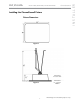
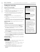
Installing the ChromaSteam3 Control Box
Control Box Dimensions
• To prevent product or property
damage, do not expose control
box to temperatures above 140
°F (60 °C). Do not locate control
box in an attic or any location
where ambient temperatures
may exceed 140 °F (60 °C).
• Do not locate control box next
to heat sources, such as hot air
registers, air conditioner con-
densers, etc.
• The control box powers the
ChromaSteam3 fixture with
5VDC 1.6A maximum.
NOTICE
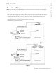
Locating the Control Box
Determine the desired location of the ChromaSteam3 control box outside
the steam room in a dry location.
IMPORTANT NOTE:
The ChromaSteam3 control cable is 30 feet long.
Ensure that the ChromaSteam3 fixture and control box are located accord-
ingly. Contact MrSteam to purchase an optional 60-foot cable (PN104268-60).
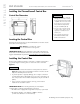
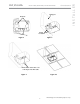
Installing the Control Box
Using screws and washers, affix the control box to a stable vertical surface
(e.g., stud) using the mounting holes on either side of the control box
(Figure 4).
• The control box must be mounted in a vertical position as shown in
Figure 4 to allow proper heat dissipation. Failure to mount as shown
may cause thermal protection shut off.
• To prevent product or property damage, do not expose control box
to temperatures above 140 °F (60 °C). Do not locate control box in an
attic or any location where ambient temperatures may exceed 140 °F
(60 °C).
• In the event the control box requires servicing, ensure that it is
installed in an accessible location.
IMPORTANT NOTE:
The following materials (not included) are
recommended to install the ChromaSteam3 control box:
• Two #10 screws of appropriate length with round, truss, or pan head.
• Two washers with 0.5” outer diameter x 0.0625” thickness
(12 mm outer diameter x 1.5 mm thickness).
Figure 4
Shock hazard. Do not place the control
box in a location where it can get wet.
WARNING
!
NOTICE