
Residential Generator Install Manual

I N S T A L L E R
14
OPTIONAL AUTOFLUSH
®
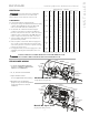
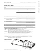
Box Contents
AutoFlush Valve with Cord
Installation Instructions.
OPERATION
The optional AutoFlush System feature automatically drains
the MrSteam generator following each use. A time delay
allows the water to cool down (about two hours) before it
drains by gravity for a safe and gentle operation.
NOTE:
If the Express Steam
®
option has been installed, the
AutoFlush will drain for ten minutes then refill with fresh water
to begin the pre-heat cycle.
INSTALLATION INSTRUCTIONS
1. Plumbing to be performed by a qualified plumber and shall be in
accordance with applicable national and local codes. Unit drains
by gravity. A drain line that is lower than the AutoFlush
®
assembly
must be available. The AutoFlush System valve outlet is
1
⁄2“ NPT.
Check plumbing code for receptor, trap and vent requirements.
2. Use copper or brass nipple
1
⁄2“ NPT x 3
1
⁄2“ or longer (not supplied)
to connect AutoFlush valve (end "B") to the Drain Valve (valve end
“A” and “B” are indicated on bottom of AutoFlush Valve)
DO NOT REMOVE THE DRAIN VALVE
Removal may cause equipment and property damage. If there is
not enough room for the valve, an elbow and a short nipple
(not provided) can be added.
3. Open Drain Valve (handle must be aligned with brass nipple).
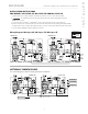
4. Connect the AutoFlush System cord connector to the three pin
connector as shown.
DO NOT drain into a steam enclosure or any location
where accidental contact with drain water may occur. In the event of
a power failure the AutoFlush System valve will open and may dis-
charge boiling water causing a scalding hazard.
SWEAT FITTINGS
When using sweat fittings use only tin base solder with a melting
point below 600 degrees F. DO NOT overheat. Ends of water supply
tubing must be thoroughly clean for a minimum distance of 1" from
ends. DO NOT remove valve cover.
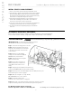
TO CHECK OPERATION
1. Turn on MrSteam and allow tank to fill with water.
2. Turn off MrSteam control. Water should stay in tank.
3. Turn off power at the panel box. Water should
discharge from tank.
4. Turn on power at panel box.
5. Repeat
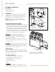
PROVIDE DRAIN PLUMBING ACCORDING TO LOCAL
CODES. PLUMB AS REQUIRED FOR AUTOFLUSH SYSTEM.
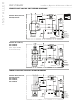
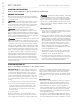
Drain Valve
DO NOT TURN OR REMOVE
THE DRAIN VALVE
(shown in the correct open
position)
Nipple
Plumb to
Drain Line
AutoFlush
Valve
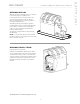
AutoFlush Shown Fully Assembled
AutoFlush Cord
AutoFlush
Valve
3 Pin Connector
for AutoFlush
AutoFlush Cord
Connector
Drain Valve
(
shown in the correct
open position)
D
O NOT REMOVE
T
HIS DRAIN VALVE
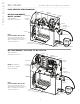
Steam Generator
N
ipple
c
opper or brass
nipple
1
⁄
2
" NPT x 3
1
⁄
2
" or
l
onger
(
not supplied)
End
"B"
E
nd
"A"
P
lumb to
Drain Line
Arrow indicates correct direction of flow
Steam Generator
mr
.
steam
®
Installation, Operation & Maintenance Manual
__________________________________________________________________________
All drawings are for illustrative purposes only
WARNING
!
CAUTION
!
CAUTION
!