
Installation Guide
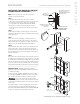

STEAM OUTLET (
1
⁄
2
" NPT)
1. DO NOT install any valve in steam line. Flow of steam must
be unobstructed.
2. Use 1/2-inch brass pipe or copper tubing from unit to steam
head as permitted by codes.
3. Insulate steam line with fiberglass pipe insulation or similar
insulation rated 212° F or higher.
4. Pitch steam line 1/4" per foot towards steam head or steam
generator to avoid valleys and trapping of condensate.
NOTE: Running the steam line down and then up will create a
steam trap blocking the flow of steam.
NOTE: A 1.5" hole in the steam room is required to mount the
steamhead.
SAFETY VALVE (
3
⁄
4
" NPT)
Where permitted by local codes, provide an outlet plumbing
connection for safety valve.
To insure proper and automatic safety valve
operation: DO NOT connect a shut off valve or a plug at safety
valve outlet. DO NOT connect a shut off valve or any obstruc-
tion in steam supply pipe. DO NOT connect the safety-valve
output into the steam line.
DRIP PAN
MrSteam strongly recommends the use of a drip pan in the
unlikely event of a plumbing leak. Check local plumbing codes
for receptor, trap and vent requirements. Drip pans drain by
gravity. The drip pan is equipped with an integral
3
/
4
" fitting.
See page 15 for additional drip pan installation information.
NOTE: Do not plumb the generator drain and drip pan drain
together in such a way that will cause drain water to back into
drip pan.
AROMASTEAM
If the optional AromaSteam Electronic Oil Delivery System
(
PN
:
MS AROMA
) is to be installed, a 90 degree T plumbing
fitting must be installed at a designated location on the steam
outlet line. See the MrSteam AromaSteam Operation and
Instruction Manual (
PN
: 100402) for installation information
before the steam line is installed at the technical downloads
section of www.mrsteam.com
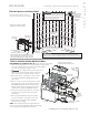
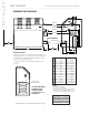
INSTALLATION
PLUMBING
All plumbing shall be performed by a qualified licensed plumber
and in accordance with applicable National and local codes.
1. Use unions on all pipe connections.
2. Use only brass piping or rigid copper tubing as permitted
by codes.
3. DO NOT use black, galvanized, PVC pipe or PEX except as
noted below.
WATER SUPPLY (
3
⁄
8
" NPT)
1. Connect to cold water line.
NOTE: Water feed line may be flexible copper tubing, braided
hose, PVC or PEX if permissible by local codes.
2. Provide a shut off valve in the water supply line upstream of
the steambath generator.
3. DO NOT overheat inlet solenoid valve with solder connections.
Overheating will damage parts.
4. Flush inlet water line thoroughly before making connection
to unit.
5. Strainer recommended upstream of feed water connection.
6. In order to reduce operating noise, reducing feed water pres-
sure to between 15 - 20 psi is recommended. Optional pres-
sure reducing valve part number 104198.
7. Provide anti-water hammer device as required.
8. Install an approved backflow preventer as required
by local codes.
DRAIN (
1
⁄
2
" NPT)
The drain from the generator should not share an
undersink trap, unless the generator is mounted higher than the
sink to prevent damage to the generator if the drain backs up.
NOTE: A drain valve is provided to facilitate servicing. Provide a
drain line connection from steambath generator drain valve
according to National and local Codes. Check local plumbing
code for receptor, trap and vent requirements. Do not connect
Drain line and Safety Valve line together. Unit drains by gravity.
NOTE: Do not plumb the generator drain and drip pan drain
together in such a way that will cause drain water to back into
drip pan.
DO NOT drain into a steam enclosure or any
location where accidental contact with drain water may occur. In
the event of a power failure the AutoFlush System valve will
open and may discharge boiling water causing a scalding hazard.
DO NOT connect the drain valve to the steam line
6
I N S T A L L E R
mr
.
steam
®
Installation, Operation & Maintenance Manual
__________________________________________________________________________
WARNING
!
WARNING
!
CAUTION
!