
Instructions / Assembly


24
CHROMASTEAM3 INSTALLATION
CHROMASTEAM3 INSTALLATION
Figure 2
Figure 4
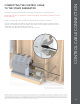
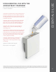
ChromaSteam3
LED Fixture
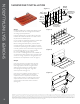
Figure 1
ChromaSteam3
Controller
ChromaSteam3
Fixture
ChromaSteam3 cable (30ft)
Grounded
Wall Outlet
Power Cord (6 ft)
iSteam3
Steam Room
(Wet)
(Dry)
In-Room Control Cable (30/60 ft)
ChromaSteam3
Control Box
Steam
Generator
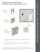
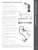
Step 1. Locating the control box. Deter-
mine the desired location of the ChromaS-
team3 control box outside the steam room
in a dry location. (Fig.1)Step 2. Installing
the control box. Using screws and wash-
ers, affix the control box to a stable vertical
surface (e.g., stud) using the mounting holes
on either side of the control box (Figure
2).Step 3. Install junction box. Remove
one of the four knockouts from the junction
box. The resulting hole will allow routing of
the 30-foot control cable into the junction
box. Locate the two tabs on the junction
box, and line them up against a ceiling joist.
The tabs locate the junction box proud of
(slightly raised from) the joist. Screw the
two screws into the ceiling joist to secure
the junction box (Figure 3).
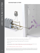
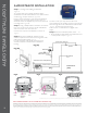
Step 4. To install the fixture: 1. Connect
the ChromaSteam3 fixture’s pigtail to the
30-foot control cable in the junction box
(Figure 4). 2. Clean the surface of the ceiling
to ensure the double-stick adhesive of the
fixture bonds completely to the ceiling.
3. Peel off and discard the protective layer
from the fixture’s double-stick adhesive
(Figure 5). 4. Squeeze the retention springs
on the back of the fixture and fit them into
the junction box (Figure 6). Insert the fix-
ture into the junction box and affix it to the
ceiling, being careful not to pinch the pigtail/
control cable. Press firmly around edges of
the fixture to ensure adhesion to ceiling.
5. Apply a bead of silicone around the
perimeter of the fixture (Figure7) as
required to create a moisture seal between
the fixture and the steam room ceiling.
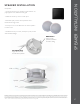
Step 5. Connecting ChromaSteam3
Fixture to ChromaSteam3 Control Box.
Remove the two cover screws from the
front of the control box and remove the
cover from the unit. Insert the free end of
the control cable into the control box’s
LED receptacle (Figure 8).
Step 5. Connecting the ChromaSteam3
control box to the steam generator. Re-
move the cover and knockout on steam
generator. Connect the controller cord
directly to the steam generator’s circuit
board (A in Figure 9), OR if an additional
accessory is installed in the steam generator,
connect the controller cord to the supplied
daughterboard (B in Figure 9). Plug the
ChromaSteam3 control box power cord
into a 120V grounded electrical outlet.
Figure 3
Ceiling Joist
Junction Box
Tabs
Figure 5
Figure 6
Figure 7
Figure 8
Adhesive
Protective layer
Pigtail
Figure 9
ChromaSteam3
Control Box Cord
Steam Generator
circuit board
Steam Generator
circuit board
ChromaSteam3
Control Box Cord
Knockout
Daughterboard
Steam Generator
circuit board
ChromaSteam3
Control Box Cord
A
B
For Illustrative purposes only. Consult with
qualified designer, architect or contractor
for steamroom construction details.
IMPORTANT The information in this guideline is designed to provide a general overview of how MrSteam products are installed. The diagrams are for Illustrative purposes only. NEVER use this document for the Installation,
Operation or Maintenance of any MrSteam product. For Installation, Operation and Maintenance information, only use the specic Installation, Operation and Maintenance manual supplied with each Mr. Steam product. The
specic Installation, Operation and Maintenance manual that is supplied with each Mr. Steam product contains important information required for the safe and reliable installation and operation of the product. Failure to use
the specic Installation, Operation and Maintenance manual that is supplied with each Mr. Steam product may result in product damage, property damage, death or personal injury. If you do not have an Installation, Operation
and Maintenance manual please contact MrSteam for a free copy, or download a copy from www.mrsteam.com. If you have any questions about the installation, operation or maintenance of any MrSteam product please
contact a customer or technical service representative using the contact information on the back cover of this guideline.
Note: ChromaSteam3 to be used with the iSteam3 only.