
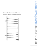
Operating Guide
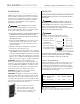


ELECTRICAL CONNECTIONS
TO PREVENT SHOCK HAZARD, THE
ELECTRICITY MUST BE TURNED OFF AT THE MAIN
PANEL BEFORE ANY WIRING
IS ATTEMPTED.
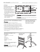
The towel warmer is an electric device.
It must be installed by a licensed electrician in accordance
with the National Electrical Code (NEC) and local code.
Installation of a wall switch or timer to
turn the towel warmer on and off is required.
NOTE: When the towel warmer is energized (ON), the indi-
cator light on the towel warmer will illuminate.
NOTE:
The Towel Warmer wires are color coded: BLACK for
LINE, WHITE for NEUTRAL, GREEN/YELLOW for EQUIP-
MENT GROUND.
Install Towel Warmers in upright position
only. Locate with wiring box and pilot light on bottom as
shown on pages 4 & 5. Failure to install properly may result in
overheating and a hazardous condition.’
All wiring must conform to National Electrical Code (NEC)
and local code.
mr
.
steam
®
towelwarmers
Installation, Operation & Maintenance Instructions
_______________________________________________________________
6
Wiring Box
Set Screw(s)
Wiring Box
Wiring Box
Field
Wires
W
iring Box
Escutcheon
Wiring Box
Escutcheon
B
X Connector
Lock Nut
B
X Cable*
(or greenfield)
Wires from
wiring box
!
WA RN IN G
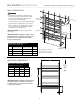
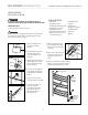
1. Assemble the BX cable
connector to the wiring box
escutcheon as shown.
NOTE: NM (non-metallic) cable,
if permitted by National and
Local Codes, may be used
instead of BX cable
2. Secure wiring box escutcheon
to the wall with screws
provided. (Use longer screws
as required by construction
conditions.)
3. Connect wiring per
instructions.
4. Slide the wiring box into the
wiring box escutcheon and
tighten the set screw firmly.
Secure the upper and lower
brackets per the instructions
on page 5.
!
WA RN IN G
!
WA RN IN G
!
CA UT IO N
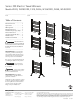
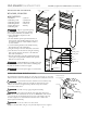
Instructions for Installing a 300 Series Towel Warmer with a Junction Box.
A wall plate is required to complete this installation. Available wall plates:
Polished Chrome 104093PC Oil Rubbed Bronze 104093ORB White 104093WH
Field
Wires
Wires from
Wiring Box
Wiring Box
Wiring
Box Set
Wiring
Box
Wiring Box
Escutcheon
Wall
Plate
Screws
1. Assemble the bushing to
the wall plate and wiring
box escutcheon as shown.
2. Secure the assembly to
the junction box using
the screws provided
with the wall plate.
3. Connect wires
per instructions
4. Slide the wiring box into the
wiring box escutcheon and
tighten the set screw firmly.
Secure the upper threaded
flanges and lower brackets
with screws provided.