Please read this manual carefully before installation and keep it for future reference. Installation Manual Advantage Series Please keep this manual where the operator can easily find it. Inside you will find helpful hints on how to use and maintain your unit properly.
Contents 0 Safety Precautions ................................... 3 1 Accessories .................................................. 5 2 Installation Summary - Indoor Unit ....... 7 3 Parts ................................................................. 9 4 Indoor Unit Installation ......... 10 1. Installation location .................................... 10 2. Attach mounting plate to wall ................11 3. Drill wall hole for connective piping ...... 11 4. Prepare refrigerant piping ..............
Contents 6 Refrigerant Piping Connection ........ 24 A. Note on Pipe Length ............................................................. 24 B. Connection Instructions –Refrigerant Piping ...............24 1. Cut pipe ............................................................................... 24 2. Remove burrs..................................................................... 25 3. Flare pipe ends ................................................................. 25 4. Connect pipes..................
Safety Precautions Read Before Installation Incorrect installation may cause serious damage or injury. The seriousness of potential damage or injuries is classi�ed as either WARNING a or CAUTION. This symbol indicates ignoring instructions may cause death or serious injury. WARNING This symbol indicates that ignoring instructions may cause moderate injury to your person, damage to your unit, or other property. CAUTION This symbol indicates that you should never perform the indicated action.
Safety Precautions WARNING 6. For all electrical work, follow all appropriate wiring standards, regulations, and the Installation Manual. You must use an independent circuit and single outlet to supply power. Do not connect other appliances to the same outlet. Insu f re. 7. y, and clamp them securely to prevent external forces from damaging the terminal. Improper electrical connections may overheat re, or shock. 8.
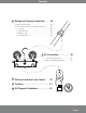
1 Accessories The air conditioning system includes the following accessories. Use all of the installation parts and accessories to install the air conditioner. Improper installation may result in water leakage, electrical shock re, or cause equipment failure. Name Shape Quantity Mounting plate 1 Clip anchor 5 Mounting plate fixing screw ST3.9 X 25 5 Remote control 1 Fixing screw for remote controller holder ST2.9 x 10 2 Remote control holder 1 Optional Parts Dry battery AAA.
Accessories Shape Name Quantity INVERTER SPLIT-TYPE ROOM AIR CONDITIONER Owner’s Manual Owner’s Manual All Model Numbers 1 CS78421-548-754 IMPORTANT NOTE: Read this manual carefully before installing or operating your new air conditioning unit. Make sure to save this manual for future reference. INVERTER SPLIT-TYPE ROOM AIR CONDITIONER Installation Manual Installation Manual 1 CS78421-548-754 IMPORTANT NOTE: Read this manual carefully before installing or operating your new air conditioning unit.
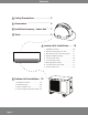
Installation Summary - Indoor Unit 1 2 5.9in (15cm) 4.75in (12cm) 2 4.75in (12cm) 90.55in (2.
Installation Summary - Indoor Unit 5 6 7 L Connect Piping (Page 24) N S Connect Wiring (Page 16) Prepare Drain Hose (Page 13) 8 Wrap Piping and Cable (Page 17) 9 STEP 8 Mount Indoor Unit (Page 17) Page 8
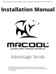
3 Parts Wall Mounting Plate Front Panel Power Cable (Specified Units) Louver Drainage Pipe Functional Filter (On Front of Main Filter - Specified Units) Signal Cable Refrigerant Piping Remote Control Remote Holder (Specified Units Outdoor Unit Power Cable (Specified Units) Fig. 2.1 NOTE ON ILLUSTRATIONS Illustrations in this manual are for explanatory purposes. The actual shape of your indoor unit may vary.
4 Indoor Unit Installation Installation Instructions – Indoor Unit PRIOR TO INSTALLATION Before installing the indoor unit,refer to the label on the product box to make sure that the model number of the indoor unit matches the model number of the outdoor unit. Step 1: Select installation location Before installing the indoor unit, you must choose an appropriate location. The following are standards will help you choose an appropriate location.
Indoor Unit Installation Refer to the following diagram to ensure proper distance from walls and ceiling: 5.9in (15cm) or more 4.75in (12cm) or more 4.75in (12cm) or more Fig. 3.1 90.55in (2.3m) or more Step 2: Attach mounting plate to wall Step 3: Drill wall hole for connective piping The mounting plate is the device on which you will mount the indoor unit.
Indoor Unit Installation 13.7in (348.4mm) 4in (101mm) 1.95in (49mm) 5.35in (136mm) 1.95in (49mm) Indoor unit outline Left rear wall hole 2.5in (65mm) 28.45in (722mm) Right rear wall hole 2.5in (65mm) Model A 0.2 - 0.3in ( 5 - 7 mm ) 16.8in (426mm) 1.7in (43mm) 5.05in (128mm) 1.7in (43mm) 9.15in (232mm) 7.55in (192mm) Indoor unit outline Left rear wall hole 2.5in (65mm) 1.7in (43mm) 11.7in (297mm) Fig. 3.2 Fig.3.2 1.45in (37mm) 7.05in (179mm) Outdoor 11.
Indoor Unit Installation Step 4: Prepare refrigerant piping The refrigerant piping is inside an insulating sleeve attached to the back of the unit.You must prepare the piping before passing it through the hole in the wall. Refer to theRefrigerant Piping Connection section of this manual for detailed instructions on pipe �aring and �a re torque requirements, technique, etc. 1. Based on the position of the wall holerelative to the mounting plate, choose the side rom f which the piping will exit the unit. 2.
Indoor Unit Installation Step 5: Connect drain hose By default, the drain hose is attached to the lefthand side of unit (when you’re facing the back of the unit). However, it can also be attached to the right-hand side. Make sure there are no kinks or dent in the drain hose to ensure proper drainage. 1. To ensure proper drainage, attach the drain hose on the same side that yourrefrigerant piping exits the unit. 2. Attach drain hose extension (purchased separately) to the end of drain hose. T 3.
Indoor Unit Installation BEFORE PERFORMING ELECTRICAL WORK, READ THESE REGULATIONS 1. All wiring must comply with local and national electrical codes, and must be installed by a licensed electrician. 2. All electrical connections must be made according to the Electrical Connection Diagram located on the panels of the indoor and outdoor units. 3. If there is a serious safety issue with the power suppl y, stop work immediately.
Indoor Unit Installation Step 6: Connect signal cable The signal cable enables communication between the indoor and outdoor units. You must �rst choose the appropriate cable size before preparing it for connection.
Indoor Unit Installation 6. Feed the signal wire through this slot, from the back of the unit to theront. f 7. Facing the front of the unit, match the wi re colors with the labels on the terminal block, rew each wire to its corresponding terminal. CAUTION DO NOT MIX UP LIVE AND NULL WIRES This is dangerous, and can cause the air conditioning unit to malfunction. 8. After checking to make sure every conn ection is secure, use the cable clamp to fasten the signal cable to the unit.
Indoor Unit Installation If refrigerant piping is already embedded in the wall, do the following: 1. Hook the top of the indoor unit on the upper hook of the mounting plate. 2. Use a bracket or wedge to p rop up the unit, giving you enough room to connect the refrigerant piping, signal cable, and drain hose. Refer toFig. 3.13 for an example. 3. Connect drain hose andrefrigerant piping (refer to Refrigerant Piping Connection section of this manual for instructions). 4.
5 2 4 i n (6 0 cm) a b o ve Outdoor Unit Installation Installation Instructions – Outdoor Unit Step 1: Select installation location Before installing the outdoor unit, you must choose an appropriate location. The following standards will help you choose an appropriate location. Proper installation locations meet the following standards: Meets all spatialrequirements shown in Installation Space Requirements (Fig. 4.
Outdoor Unit Installation SPECIAL CONSIDERATIONS FOR EXTREME WEATHER If the unit is exposed to heavy wind: Install unit so that air outlet fan is at a 90° angle to the direction of the wind. If needed, build a barrier in front of the unit to protect it from extremely heavy winds. Ensure the wind barrier does not block necessary air flow. See Fig. 4.2 and Fig. 4.3 below. Strong wind If the drain joint comes with a rubber seal (see Fig. 4.4 - A), do the following: 1.
Outdoor Unit Installation Step 3: Anchor outdoor unit The outdoor unit can be anchored to the ground or to a wall-mounted bracket. W A Air inlet UNIT MOUNTING DIMENSIONS B Air inlet D The following is a list of different outdoor unit sizes and the distance between their mounting feet. Prepare the installation base of the unit according to the dimensions below. Outdoor Unit Dimensions (in/mm) W Air outlet Fig. 4.5 A Air inlet Mounting Dimensions WxHxD Distance A (in/mm) 26.8”x17”x11.
Outdoor Unit Installation If you will install the unit on a wall-mounted bracket, do the following: CAUTION Before installing a wall-mounted unit, make sure that the wall is made of solid brick, concrete, or of similarly strong material. The wall must be able to support at least four times the weight of the unit. 1. Mark the position of bracket holes based on dimensions in the Unit Mounting Dimensions chart. 2. Pre-drill the holes for the expansion bolts. 3. Clean dust and debris away rom f holes. 4.
Outdoor Unit Installation PAY ATTENTION TO LIVE WIRE WARNING BEFORE PERFORMING ANY ELECTRICAL OR WIRING WORK, TURN OFF THE MAIN POWER TO THE SYSTEM. 1.
6 Refrigerant Piping Connection Note on Pipe Length The length of refrigerant piping will affect the performance and energy ef�ciency of the unit. Nominal ef�ciency is tested on units with a pipe length of 16.5ft (5 meters). Refer to the table below for speci�cations on the maximum length androp d height of piping. Maximum Length and Drop Height of Refrigerant Piping per Unit Model Model R410A Inverter Split Air Conditioner Capacity (BTU/h) Max. Length (ft/m) Max.
Refrigerant Piping Connection DO NOT DEFORM PIPE WHILE CUTTING Flare nut Be extra careful not to damage, dent, or deform the pipe while cutting. This will drastically reduce the heating ef unit. Copper pipe Step 2: Remove burrs Burrs can affect the air-tight seal ofrefrigerant piping connection. They must be completely removed. Fig. 5.3 1. Hold the pipe at a downward angle to prevent burrs from falling into the pipe. 4. Remove PVC tape rfom ends of pipe when r 2.
Refrigerant Piping Connection 6. 7. Tur 8. Instructions for Connecting Piping to Indoor Unit red. re form, then inspect the end of the pipe for cracks and 1. Align the center of the two pipes that you will connect. See Fig. 5.7. Step 4: Connect pipes When connecting refrigerant pipes, be careful not to use excessive torque or to deform the piping in any way. You should �rst connect the low-pressure pipe, then the high-pressure pipe.
Refrigerant Piping Connection Instructions for Connecting Piping to Outdoor Unit USE SPANNER TO GRIP MAIN BODY OF VALVE Torque fr off other parts of valve. 1. Unscrew the cover from the packed valve on the side of the outdoor unit. (SeeFig. 5.9) re nut can snap Valve cover Fig. 5.9 2. Remove protective caps from ends of valves. 3. hand. red pipe end with each valve, and re nut as tightly as possible by 4. Using a spanner, grip the body of the valve. Do not grip the nut that seals the service valve.
7 Air Evacuation MC Preparations and Precautions Air and foreign matter in therefrigerant circuit can cause abnormal rises in pressure, which can damage the air conditioner, reduce its ef�ciency, and cause injury. Use a vacuum pump and manifold gauge to evacuate therefrigerant circuit, removing any non-condensable gas and moisture from the system. Evacuation should be performed upon initial installation and when unit isrelocated.
Air Evacuation 3. Open the Low Pressure side of the manifold gauge. Keep the High Pressure side closed. 4. Turn on the vacuum pump to evacuate the system. 5. Run the vacuum for at least 15 minutes, or until the Compound Meterreads -76cmHG (-105 Pa). 6. Close the Low Pressure side of the manifold gauge, and turn off the vacuum pump. 7. Wait for 5 minutes, then check that the re has been no change in system pressure. 8.
Electrical and Gas Leak Checks Electrical Safety Checks After installation, con�rm that all electrical wiring is installed in accordance with local and national regulations, and according to the Installation Manual. BEFORE TEST RUN Check Grounding Work Measure grounding resistance by visual detection and with grounding resistance tester. Grounding resistance must be less than 4. Note: This may not berequired for some locations in the US.
9 Test Run Before Test Run Only perform test run after you have completed the following steps: • Electrical Safety Checks – Con�rm that the electrical system is safe and operating properly • Gas Leak Checks – Check all �a re nut connections and con�rm that the system is not leaking • Con�rm that gas and liquid (high and low pressure) valves are fully open Test Run Instructions You should perform theTest Run for at least 30 minutes. 1. Connect power to the unit.
Testing DOUBLE-CHECK PIPE CONNECTIONS During operation, the pressure of the refrigerant circuit will increase. This may reveal leaks that were not present during your initial leak check.Take time during theTest Run to double-check that allrefrigerant pipe connection points do not have leaks. Refer to Gas Leak Check section for instructions. 5. After the Test Run is successfully complete, of Checks to Perform havePASSED, do the following: Manual control button a.
EU Disposal Guidelines 10 This appliance contains refrigerant and other potentially hazardous materials. When disposing of this appliance, the lawrequires special collection and treatment. Do not dispose of this product as household waste or unsorted municipal waste. When disposing of this appliance, you have the following options: • Dispose of the appliance at a designated municipal electronic waste collection facility.
Advantage Series The design and specifications are subject to change without prior notice. Consult with the sales agency or manufacturer for details.