Please read this manual carefully before installation and keep it for future reference. Owner & Installation Manual DIY E Star Series ® ™ Please read this manual carefully before installation and keep it for future reference.
Contents ! Safety Precautions 1 Parts Overview 2 Operating Instructions 3 Care and Maintenance Warnings ................................................................................................................................. Cautions .................................................................................................................................. Parts Diagram ...................................................................................................................
Contents 4 Indoor Unit Installation ...........15 1. Installation location................................15 2. Attach mounting plate to wall...............16 3. Drill wall hole for connective piping.....16 4. Prepare refrigerant piping ....................18 5. Connect refrigerant piping ....................19 6. Connect drain hose.................................21 7. Wrap piping and cables..........................22 8. Mount indoor unit..................................22 5 Outdoor Unit Installation ..
Safety Precautions Safety Precautions Read Before Using ! Incorrect usage may cause serious damage or injury. The seriousness of potential damage or injuries is classified as either a WARNING or CAUTION. This symbol indicates ignoring instructions may cause death or serious injury. WARNING This symbol indicates that ignoring instructions may cause moderate injury to your person, damage to your unit, or other property. CAUTION This symbol indicates that you should NEVER perform the indicated action.
Safety Precautions 7. For all electrical work, fuse the specified cables. Connect cables tightly, and clamp them securely to prevent external forces from damaging the terminal. Improper electrical connections may overheat, causing fire and/or electrical shock. 8. All wiring must be properly arranged to ensure that the control board cover can close properly.
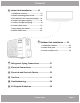
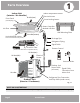
Parts Overview Indoor Unit (Interior / Air Handler) Indoor temperature sensor Electrical Access Air inlet (rear) Front Panel 1 Safety Precautions Forced cooling button (with display) Smart Controller Module USB Port Air Filter Wall Mounting Plate Vertical Airflow Louver Air outlet (bottom) Drainage Pipe Horizontal Airflow Grill (inside) Refrigerant Piping Signal Cable Fresh Air Filter (on back of main filter in Specified Units) Remote Control Air inlet (rear) Air inlet (side) Electrical Access
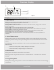
Overview - Display 1 2 ° ECO 3 4 Fig. 1.2 Display (on front panel of indoor unit) see fig. 1.2 1. Digital Display: Displays the Temperature Setting when the air conditioner is operational. Displays the Room Temperature when in FAN mode. Displays the self-diagnostic codes. Displays “ON” for three seconds when the Timer is ON and/or Fresh, Swing, Turbo or Silence feature is activated. Displays “OF” for three seconds when the Timer is switched OFF.
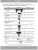
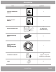
Accessories The air conditioning system includes the following accessories. Use all of the installation parts and accessories to install the air conditioner. Improper installation may result in water leakage, electrical shock, fire, or equipment failure. PART LOOKS LIKE... QUANTITY Mounting plate 1 Anchor 5 Mounting plate fixing screw 5 Remote control 1 Fixing screw for remote controller holder ST2.9 x 10 2 Remote control holder 1 Optional Parts Dry battery AAA.
Accessories PART LOOKS LIKE... QUANTITY Please read this manual carefully before installation and keep it for future reference. Owner’s Manual Owner & Installation Manual 1 E-Star™ DIY Series For more details visit www.MrCool.com Please read this manual carefully before installation and keep it for future reference. Remote Control Manual Remote Control User Manual 1 For more details visit www.MrCool.
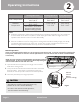
Safety Precautions Operating Instructions Cooling Operation Room Temperature Outdoor Temperature 2 Heating Operation Drying Operation (17°C~32°C) 63°F~90°F (0°C~50°C) 32°F~122°F 5°F~122°F / -15°C~50°C (For the models with low ambient cooling system) (0°C~30°C) 32°F~86°F (10°C~32°C) 50°F~90°F (-15°C~24°C) 5°F~75°F (0°C~50°C) 32°F~122°F NOTE: 1. Optimum performance will be achieved within these operating temperatures.
Operating Instructions Airflow Directional Control · Adjust the airflow direction properly. Otherwise, it might cause discomfort or uneven room temperatures. · Adjust the vertical louver using the remote. · Adjust the horizontal louver manually. Adjust Vertical (Up / Down) Air Flow using Vertical Louver (fig2.2): Perform this function while the unit is in operation. Use the remote control to adjust the Vertical Louver / Vertical Air Flow direction.
Operating Instructions Basic Operation Modes: AUTO / COOL / DRY / HEAT (Model dependent). How the air conditioner works Auto Operation: When you set the air conditioner in AUTO mode, it will automatically select cooling, heating or fan-only operation depending on set temperature and room temperature. 8 hours timer OFF SLEEP operation The unit will control the room temperature automatically, according to the temperature point you set.
Operating Instructions Special Functions Refrigerant Leakage Detection (optional): When refrigerant leakage is detected, the indoor unit will display “EC” or “ELOC” code or flash LEDs, depending on the model. Louver Angle Memory Function (optional): Within the scope of the safe operation angle, the horizontal louver angle is memorized and returns to the position last selected by the user. If it exceeds the safe operation angle, it will default within the safe operation range.
Operating Instructions Care and Maintenance 3 CAUTION Power supply must be disconnected before attempting to clean or service. Failure to do so can cause electrical shock. DO NOT use benzene, thinner, polishing powder, or similar solvents for cleaning. These may cause the plastic to crack and/or deform. DO NOT use a chemically treated cloth or duster to clean the unit. DO NOT touch air freshening (Plasma) filter for at least 10 minutes after turning off the unit.
Care and Maintenance 3 3. Then, extract the filter by gently drawing it downward. Replace as necessary. 4. Unclip the small air freshening filter from the larger air filter. Replace as necessary. Otherwise, clean it with a vacuum and clip it back into place after cleaning the larger air filter as outlined in step 5. 5. Clean the large air filter with warm, soapy water. Be sure to use a mild detergent. Rinse with fresh water. Shake off excess water and dry in a cool area. 6.
Installation Summary - Indoor Unit Indoor Unit Installation DO NOT install unit in the following locations: Installation Instructions – Indoor Unit Near any source of heat, steam, or combustible gas PRIOR TO INSTALLATION: Before installing the indoor unit, refer to the label on the product box to make sure that the model number of the indoor unit matches the model number of the outdoor unit.
Indoor Unit Installation Refer to the following diagram to ensure proper distance from walls and ceiling: Minimum Ceiling Clearance is 15cm (5.9in) >12cm (4.75in) >12cm (4.75in) For Ceilings GREATER Than 9 Foot, Suggested Floor Clearance is 230cm(90.55in) For Ceilings LESS Fig. 4.1 Than 9 Foot, Suggested Floor Clearance is 200cm(78.55in) Step 2: Attach mounting plate to wall Step 3: Drill wall hole for connective piping The mounting plate is the device on which you will mount the indoor unit.
Indoor Unit Installation Outdoor 426mm(16.8in) 43mm (1.7in) 43mm (1.7in) 297mm (11.7in) Indoor unit outline Left rear wall hole 90mm (3.5in) 0.2 - 0.3in (5 - 7 mm) 128mm (5.05in) 802mm (31.6in) Right rear wall hole 90mm (3.5in) Series 12K Models 517.4mm(20.37in) 144mm (5.65in) MOUNTING PLATE DIMENSIONS Left rear wall hole 90mm (3.5in) Indoor unit outline 34mm (1.35in) Different models have different mounting plates.
Indoor Unit Installation Step 4: Prepare refrigerant piping NOTE ON PIPING ANGLE The refrigerant piping is inside an insulating sleeve attached to the back of the unit. You must prepare the piping before passing it through the hole in the wall. Refer to the Refrigerant Piping Connection section of this manual for detailed instructions on torque requirements, technique, etc. Refrigerant piping can exit the indoor unit from two different angles: Left-hand side Right-hand side Refer to Fig. 4.4 for details.
Indoor Unit Installation Step 5: Connect Refrigerant Piping to Indoor Unit Refrigerant Pipe Connectors (both ends): 5.1 Tools needed You will require the following tools to carry out this installation work correctly: •1x crescent wrench, 19 mm •1x crescent wrench, 22 mm/24mm •1x crescent wrench, 24 mm/27mm •1x Allen key, 5 mm •1x Philips screwdriver •1x leak detection spray or alternatively soap suds (water/detergent mix) 5.
Indoor Unit Installation TORQUE REQUIREMENTS 1. Excessive force can break the nut or damage the refrigerant piping. You must not exceed torque requirements shown in the table below. 2. You can find the Outer Pipe Diameter stamped (in inches) on the valve set of the condenser. Refer to this when finding and applying the torque values in the table below. 3. Note that there may be differences in Torque Wrenches (i.e.
Indoor Unit Installation Make sure there are NO kinks or dents in the hose to ensure proper drainage. Step 6: Connect drain hose By default, the drain hose is attached to the left-hand side of unit (when you’re facing the back of the unit). However, it can also be attached to the right-hand side. 1. To ensure proper drainage, the drain hose must exit the unit on the same side as the refrigerant piping. 2. Wrap the connection point firmly with included tape Fig. 4.
Indoor Unit Installation Step 7: Wrap piping and cables DO NOT WRAP ENDS OF PIPING Before passing the piping, drain hose, and signal cable through the wall hole, you must bundle them together to protect them, and tightly wrap them together with the provided tape. When wrapping the bundle, keep the ends of the piping unwrapped. You need to access them to test for leaks at the end of the installation process (refer to Electrical Checks and Leak Checks section of this manual). 1.
5 Indoor Unit Installation Outdoor Unit Installation 24in (60cm) above 79in (200 cm) in front Installation Instructions – Outdoor Unit Step 1: Select installation location Before installing the outdoor unit, you must choose an appropriate location. The following standards will help you choose an appropriate location. 12in (30cm) on left Ground Installed: 12 in (30 cm) Bracket Installed: 6 in (15 cm) clearance between back and wall 24in (60cm) on right Fig. 5.
Outdoor Unit Installation If the drain joint comes with a rubber seal (see Fig. 5.4 - A), do the following: SPECIAL CONSIDERATIONS FOR EXTREME WEATHER If the unit is exposed to heavy wind: Install unit so that air outlet fan is at a 90° angle to the direction of the wind. If needed, build a barrier in front of the unit to protect it from extremely heavy winds. Ensure the wind barrier does not block necessary air flow. See Fig. 5.2 and Fig. 5.3 below. 1.
Outdoor Unit Installation A Air Inlet D H Air Inlet B Air Outlet W Fig. 5.5 Step 3: Anchor outdoor unit UNIT MOUNTING DIMENSIONS The outdoor unit can be anchored to the ground or to a wall-mounted bracket. The following is a list of different outdoor unit sizes and the distance between their mounting feet. Prepare the installation base of the unit according to the dimensions below.
Outdoor Unit Installation If you will install the unit on a wall-mounted bracket, do the following: Before installing a wall-mounted unit, make sure that the wall is made of solid brick, concrete, or of similarly strong material. The wall must be able to support at least four times the weight of the unit. 1. Mark the position of bracket holes based on dimensions in the Unit Mounting Dimensions chart. 2. Pre-drill the holes for the expansion bolts. 3. Clean dust and debris away from holes. 4.
66 Outdoor Unit Installation Refrigerant Piping Connection Refrigerant Piping Connection Connecting the refrigerant pipe to outdoor unit NOTE To distinguish the connectors to be connected to the indoor unit and outdoor unit, the connectors of the refrigerant pipe have been labelled “A”,“B”,“C”and “D”. Ensure the marks on the connector are the same to the indoor’s and outdoor’s respectively during connection. CAUTION For your safety, always wear goggles and work gloves when connecting the pipes.
Refrigerant Piping Connection Extend the pipe by unwinding it 1. Use your hands to slowly unwind the copper piping (Quick Connect® line set). Only unwind as much as necessary for use. 2. If the pipe is repeatedly bent or extended, it will become hard and difficult to manipulate. Avoid bending or extending the pipe for more than 3 times. 3. Do not bend the pipe excessively, otherwise it will break. MINIMUM BEND RADIUS Refer to Fig. 6.
Refrigerant Piping Connection CAUTION All of these steps must be completed BEFORE powering on the unit. Failing to do so could damage the unit. 5. Now remove the cover on the top valve using a 19 mm open ended wrench (i.e. crescent or adjustable). Open the valve by turning it counter-clockwise as far as it will go using a 5 mm Allen key. The valve is now open. If the valve is not opened fully, the system may malfunction and suffer damage.
Refrigerant Piping Connection wrapped from inside unit Quick Connect® connections Signal Cable Drainage Pipe Refrigerant Piping wrap the Quick Connect® connections with the black sound deadening pads. (Refer to section 5.3 Connecting the refrigerant pipes to indoor unit) wrap from bottom to top to ensure tape overlap sheds water coil then wrap bundled excess Fig. 6.3 Outdoor Unit (Exterior / Condenser) BEFORE PERFORMING ELECTRICAL WORK, READ THESE REGULATIONS 1.
7 Electrical Connections Connect signal and power cables The outside unit’s terminal block is protected by an electrical wiring cover on the side of the unit. A comprehensive wiring diagram is printed on the inside of the wiring cover. BEFORE PERFORMING ANY ELECTRICAL WORK, TURN OFF ALL POWER TO THE SYSTEM. Note that wire colors of this series / model may differ from previous models, other series and general conventions. All wiring must be performed in accordance with the wiring diagrams shown in Fig. 7.
Electrical Connections 2. Unscrew the electrical wiring cover and remove it. 1. Prepare the cable for connection: 3. Unscrew the cable clamp below the terminal block USE THE RIGHT CABLE • Outdoor power cable: H07RN-F • See table below for gauge requirements • Indoor power / signal cable from outdoor unit is provided (see Indoor Unit Installation) Minimum Wire Gauge for Power Cables North America Model Series Appliance Amps (A) 15 14 18K 20 12 24K 25 10 36K 35 8 4.
Refrigerant Piping Connection Electrical andand GasGas LeakLeak Checks Electrical Checks WARNING – RISK OF ELECTRIC SHOCK Electrical Safety Checks After installation, confirm that all electrical wiring is installed in accordance with local and national regulations, and according to the Installation Manual. BEFORE TEST RUN Check Grounding Work Measure grounding resistance by visual detection and with grounding resistance tester. Grounding resistance must be less than 4.
Test Run Refrigerant Piping Connection 9 Before Test Run List of Checks to Perform Only perform test run after you have completed the following steps: • Electrical Safety Checks – Confirm that the electrical system is safe and operating properly PASS/FAIL No electrical leakage Unit is properly grounded • Gas Leak Checks – Check all flare nut connections and confirm that the system is not leaking All electrical terminals properly covered • Confirm that gas and liquid (high and low pressure) valves are
Test Run DOUBLE-CHECK PIPE CONNECTIONS During operation, the pressure of the refrigerant circuit will increase. This may reveal leaks that were not present during your initial leak check. Take time during the Test Run to double-check that all refrigerant pipe connection points do not have leaks. Refer to Gas Leak Check section for instructions. 5. After the Test Run is successfully complete, and you confirm all check points in List of Checks to Perform have PASSED, do the following: a.
10 Troubleshooting The following events may occur during normal operation, and may not indicate malfunction. Symptom Cause Operation is delayed after restart To prevent blowout of the fuse, the compressor will not operate while the protection circuit is working for about 3 minutes after sudden OFF--ON operation of the power supply.
Troubleshooting Before you call to request service assistance, troubleshoot a problem by performing the following checks: Symptom Diagnostic -- Is there a power failure? Unit will not operate -- Has a switch been turned off, a circuit breaker tripped or a fuse blown? -- Is the timer operating? -- Are the batteries used in the remote controller exhausted? -- Are the batteries used in the remote controller loaded properly? -- Are the air filters dirty? -- Is air flow unrestricted in & out of indoor & outdoor
Troubleshooting Indoor Unit Error Display Operation LED Timer LED Display LED STATUS 1 time X E0 Indoor unit EEPROM parameter error 2 times X E1 Indoor / outdoor units communication error ** 3 times X E2 Zero-crossing signal detection error 4 times X E3/E88 5 times X E4 Indoor room temperature sensor T1 open circuit or short circuit 6 times X E5 Evaporator coil temperature sensor T2 open circuit or short circuit 7 times X EC Refrigerant leakage detection 2 times O F1 Outdoo
Refrigerant Piping Connection EU Disposal Guidelines 11 This appliance contains refrigerant and other potentially hazardous materials. When disposing of this appliance, the law requires special collection and treatment. DO NOT dispose of this product as household waste or unsorted municipal waste. When disposing of this appliance, you have the following options: • Dispose of the appliance at a designated municipal electronic waste collection facility.
DIY E Star Series ® ™ The design and specifications of this product and/or manual are subject to change without prior notice. Consult with the sales agency or manufacturer for details.