
Owner's Manual

Page 34mrcool.com
Electrical Connections
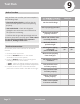
SELECT THE CORRECT CABLE
• See table below for gauge requirements
NOTE: The table below is a standard chart, the
AWG ratings and wiring needs will change based
on wire length and temperature.
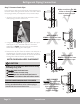
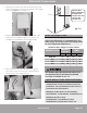
ALL WIRING MUST BE INSTALLED STRICTLY IN
ACCORDANCE WITH THE WIRING DIAGRAM
LOCATED AS SHOWN IN FIG. 7.2.
Fig. 7.2
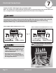
The air conditioner’s circuit board (PCB) is
designed with a fuse to provide overcurrent
protection. The specifications of the fuse are
printed on the circuit board.
EXAMPLE (Indoor Unit): T3.15AL/250VAC,
T5AL/250VAC, T3.15A/250VAC, T5A/250VAC, etc.
EXAMPLE (Outdoor Unit):
T20A/250VAC (<=18,000 Btu/h units),
T30A/250VAC (>18,000 Btu/h units), etc.
NOTE ABOUT FUSE SPECIFICATIONS
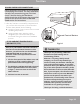
Cover
Outdoor Unit
Wiring Diagram is
located on the
inside of the wire
cover on the
outdoor unit.
Appliance
Amps (A)
AWG
25
30
35
35
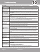
24K
18K
9K & 12K
36K
Model Series
Minimum Wire Gauge for Power Cables
MCA MOP Min. Pref.
12
10
8
8
10
8
6
6
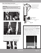
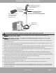
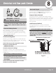
3. Now, pull the end of the MC cable through the
hole of the electrical cover you removed earlier.
Please refer to the images below.
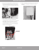
1. Remove the screws from the electrical wiring cover
from the outdoor condenser, as shown in the image
below and Fig.7.2, and remove it.
2. Remove the retaining nut from the end MC cable
that you fed through the wall hole earlier in the
installation
, as shown in the image below.
19
18
22
28